ChevyParts
My Garage
My Account
Cart
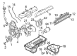
OEM 2003 GMC Safari Intake Manifold
Engine Intake Manifold- Select Vehicle by Model
- Select Vehicle by VIN
Select Vehicle by Model
orMake
Model
Year
Select Vehicle by VIN
For the most accurate results, select vehicle by your VIN (Vehicle Identification Number).
2 Intake Manifolds found


2003 GMC Safari Intake Manifold Part Number: 17113542
Product Specifications- Other Name: Manifold Kit, Engine Fuel Intake Manifold; Manifold
- Position: Upper
- Replaces: 17113213
- Item Weight: 3.30 Pounds
- Item Dimensions: 7.4 x 13.5 x 12.5 inches
- Condition: New
- Fitment Type: Direct Replacement
- SKU: 17113542
- Warranty: This genuine part is guaranteed by GM's factory warranty.
2003 GMC Safari Intake Manifold, Lower Part Number: 88894294
Product Specifications- Other Name: Manifold Kit, Lower Intake; Manifold; Manifold Kit, Engine Fuel Intake Manifold
- Position: Lower
- Item Weight: 19.50 Pounds
- Item Dimensions: 21.7 x 17.8 x 15.2 inches
- Condition: New
- Fitment Type: Direct Replacement
- SKU: 88894294
- Warranty: This genuine part is guaranteed by GM's factory warranty.
2003 GMC Safari Intake Manifold
With a comprehensive array of OEM 2003 GMC Safari Intake Manifold, from fuel pumps to door handles, our website is a one-stop-shop for your needs. All our genuine 2003 GMC Safari Intake Manifold are backed by the manufacturer's warranty and are offered at competitive prices in the market. Rest assured, you can shop with complete confidence.
2003 GMC Safari Intake Manifold Parts and Q&A
- Q: How to replace the lower intake manifold on 2003 GMC Safari?A: The replacement of a lower Intake Manifold begins with disconnecting the negative terminal of the battery and removing the engine cover. Start by draining the cooling system before taking out the air cleaner assembly and air cleaner outlet duct from the Throttle Body assembly. Begin the replacement process by detaching the throttle shaft cables for the accelerator control and cruise control mechanisms if present. Start by disconnecting the PCV Valve Hose assembly from the Intake Manifold and valve rocker arm cover before removing the nut holding both the a/c hose bracket and the engine wiring harness bracket to the Intake Manifold stud. Sequence the removal of electrical connectors for the A/C Compressor clutch , a/c high pressure cutoff switch , throttle position (TP) sensor , idle air control (IAC) motor , fuel meter body assembly connector , manifold absolute pressure (MAP) sensor , and evap canister purge solenoid valve . The engine needs its ground wire removed from the water outlet stud while the engine wire harness bracket together with its nut must be removed from the evap canister purge solenoid valve stud. Move the engine wire harness into a safe position. The technician should remove the evap canister purge valve along with the radiator inlet hose, heater hose, water pump inlet hose from the Intake Manifold as well as disconnect the vacuum hose. Remove the bolt attaching the transmission fluid filler tube to the accelerator control cable bracket before removing the accelerator control cable bracket from between the Throttle Body and Intake Manifold. First disconnect the fuel supply pipes and Distributor then remove the ignition control module (ICM) from the Intake Manifold. You must start by replacing the Drive Belt and removing the A/C Compressor side brace and loosening the Power Steering Pump rear bracket nut before you can remove the oil filler tube bracket bolt and tube. The Power Steering Pump bracket mounting bolts along with its nut need removal to make space for the A/C Compressor and the Power Steering Pump. Proceed by moving forward the Power Steering Pump bracket to reach the front Intake Manifold bolt. Thoroughly clean the surfaces on which the lower Intake Manifold seals before reinstalling it. The installation process begins by setting the engine at number one cylinder top dead center then removing the number one cylinder Spark Plug before rotating the Crankshaft to compression stroke where you must align the front cover alignment marks with Crankshaft balancer reference marks before reinstalling the Spark Plug and Distributor. Follow these steps to complete the installation: secure the lower Intake Manifold, reposition the Power Steering Pump mounting bracket and use three bolts with nuts to fasten the mounting bracket while tightening them to 41 nm (30 ft. Lbs.). Install the A/C Compressor side brace and bolts, tightening them to 25 nm (18 ft. Lbs.)insert the oil filler tube followed by installing its bolt with recommended torque setting at 25 nm (18 ft. Lbs.). Place the Drive Belt back while also installing the evap canister purge valve together with the fuel supply and return pipes. Connect the accelerator control cable bracket, tightening the nuts and studs to 12 nm (106 inch lbs.)installation of the vacuum hose occurs first followed by the transmission fluid fill tube then the water pump inlet hose along with the heater hoses and finally the radiator inlet hose. Guide the engine wiring harness and attach electrical connectors to the A/C Compressor clutch , a/c high pressure cutoff switch , throttle position (TP) sensor , idle air control (IAC) motor , fuel meter body assembly connector , map sensor , and evap canister purge solenoid valve . Install the ground wire and nut to the water outlet stud, tightening to 19 nm (14 ft. Lbs.), then install the nut and engine wiring harness bracket to the stud for the evap canister purge valve, tightening to 8 nm (71 inch lbs.)fasten the Intake Manifold stud with a torque of 12 nm (106 inch lbs.). If equipped, install the nut and a/c hose bracket to the Intake Manifold stud, tightening to 5 nm (44 inch lbs.)after completing the installation attach the PCV Valve Hose assembly to both the Intake Manifold and the valve rocker arm cover. Reinstall your cruise control cable first if it exists followed by the installation of your accelerator control cable. You must perform these final installation steps: fill the cooling system, mount the air cleaner outlet duct to the Throttle Body, and then reinstall the air cleaner assembly, reconnect the battery negative cable before reinstalling the engine cover.
Related 2003 GMC Safari Parts
 2003 GMC Safari Air Filter
 2003 GMC Safari Air Hose
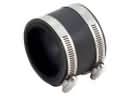 2003 GMC Safari Air Intake Coupling
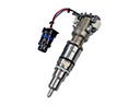 2003 GMC Safari Fuel Injector
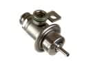 2003 GMC Safari Fuel Pressure Regulator
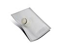 2003 GMC Safari Fuel Pump Strainer
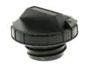 2003 GMC Safari Gas Cap
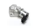 2003 GMC Safari Idle Control Valve
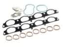 2003 GMC Safari Intake Manifold Gasket
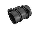 2003 GMC Safari Mass Air Flow Sensor
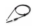 2003 GMC Safari Throttle Cable
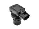 2003 GMC Safari Vapor Pressure Sensor