ChevyParts
My Garage
My Account
Cart
OEM 2005 Chevrolet Astro Fuel Injector
Gas Injector- Select Vehicle by Model
- Select Vehicle by VIN
Select Vehicle by Model
orMake
Model
Year
Select Vehicle by VIN
For the most accurate results, select vehicle by your VIN (Vehicle Identification Number).
1 Fuel Injector found


2005 Chevrolet Astro Injector Part Number: 88894353
$120.24 MSRP: $244.20You Save: $123.96 (51%)Ships in 1-2 Business DaysProduct Specifications- Other Name: Injector, Fuel Injection; Fuel Injector
- Item Weight: 0.60 Pounds
- Item Dimensions: 10.2 x 3.5 x 1.1 inches
- Condition: New
- Fitment Type: Direct Replacement
- SKU: 88894353
- Warranty: This genuine part is guaranteed by GM's factory warranty.
2005 Chevrolet Astro Fuel Injector
With a comprehensive array of OEM 2005 Chevrolet Astro Fuel Injector, from fuel pumps to door handles, our website is a one-stop-shop for your needs. All our genuine 2005 Chevrolet Astro Fuel Injector are backed by the manufacturer's warranty and are offered at competitive prices in the market. Rest assured, you can shop with complete confidence.
2005 Chevrolet Astro Fuel Injector Parts Questions & Experts Answers
- Q: How to clean the fuel injector on 2005 Chevrolet Astro?A: A proper cleaning procedure for fuel injectors requires starting with fuel fill cap loosening to let vapor pressure out of the Fuel Tank. First detach the positive crankcase ventilation clean air tube from the air inlet duct before removing the resonator and air inlet duct from the Throttle Body. Start by separating the Brake Booster Vacuum Hose and connector from the Intake Manifold because after that you will disconnect the electrical connector from the central sequential fuel injection (CSFI) fuel metering body. The vehicle owner must first remove spiral connection wires of cylinders 1, 3, and 5 from the Distributor Cap followed by unscrewing the fuel line bolt at the rear of the Intake Manifold. A fuel system pressure release should precede the detachment of fuel pipes from the metering body by removing fuel pipe nuts and clamp first. Embed j 44466-12 and j 44466-13 into the metering body while securely fastening them in place with proper fuel pipe o-ring, washer, and spacer placement. The j 44466-11 along with clamp and j 44466-13 should be attached to the fuel pipe and tightened as the next installation step. First close the valve on the tank by using the j 41413 then take off the regulator assembly before applying the j 44466-10 to the j 41413 tank. Use the j 44466-10 hose to connect with the j 44466-12 before installing the j 39021, j 39021-210, and j 39021-301 to the metering body electrical connector and set the j 39021 amperage selector switch to 0.5 amps. Presurize the fuel system through opening the tank valves and j 44466-10 while maintaining at least 150 psi pressure. The j 39021 should trigger each injector once to check the gauge pressure drop which indicates proper injector/poppet valve operation and this process needs repeating for each non-responsive injector until all perform as needed. Connect the fresh air tube to the pcv before removing the j 44466-10 from the j 44466-12 and the j 41413 following the closure of the pressure valve on the j 41413 tank while bleeding pressure off the j 44466-10. Reconnect the vehicle electrical connector after disconnecting the j 39021-301 and j 39021-210 and j 39021 from their positions on the metering body. The service worker must reinstall the Brake Booster Vacuum Hose and connector, ignition wires along with the resonator and air intake duct while hand-tightening the wing nut. Attach the j 38500-a canister to the vehicle hood and close its bottom valve before adding top engine cleaner gm p/n 1050002 (Canadian P/N 992872). Completing the mixture with regular unleaded gasoline the remaining space. The hose from j 38500-a leads to the service port on j 44466-12 until the j 38500-a valve below becomes open after which a shop air source connects through a 75 psi regulator. Drain all liquid content from the canister letting the j 38500-a stall. After shop air removal you should depressurize the j 38500-a then detach the hose from the j 44466-12 to repeat the cleaning process on pcv clean air tube, resonator, and ignition wires. After bleeding pressure from j 44466-12 the technician should take out j 44466-13 and j 44466-12 from the metering body followed by the j 44466-13 and clamp and j 44466-11 from the fuel pipe . A proper installation of the fuel pipe to the metering body requires proper spacing of o-rings along with washers and spacers before tightening the clamp and nuts to 3 n.m (27 lb ft). The fuel pipe bolt needs an application of threadlock gm p/n 12345382 (Canadian P/N 10953489) before installation with a torque of 6 n.m (53 lb ft). Reposition the brake booster vacuum components together with the connector, resonator, air inlet duct and ignition wires. The technician should add 1 oz of port Fuel Injector cleaner gm p/n 12345104 (Canadian P/N 12345515) per gallon of gasoline in the tank and advise the customer to complete the remaining bottle when refueling. Install the Fuel Tank filler cap by hand tightening and start the vehicle while conducting a fuel leak inspection. The tech ii scan tool should be used for monitoring powertrain dtc codes and code deletion. Provide the customer with advice about fuel brand changes.
Related 2005 Chevrolet Astro Parts
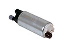 2005 Chevrolet Astro Fuel Pump
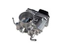 2005 Chevrolet Astro Throttle Body
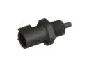 2005 Chevrolet Astro Air Charge Temperature Sensor
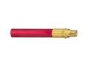 2005 Chevrolet Astro Air Hose
 2005 Chevrolet Astro Air Intake Coupling
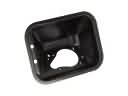 2005 Chevrolet Astro Fuel Filler Housing
 2005 Chevrolet Astro Fuel Pump Strainer
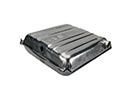 2005 Chevrolet Astro Fuel Tank
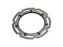 2005 Chevrolet Astro Fuel Tank Lock Ring
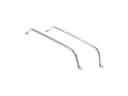 2005 Chevrolet Astro Fuel Tank Strap
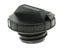 2005 Chevrolet Astro Gas Cap
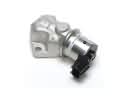 2005 Chevrolet Astro Idle Control Valve