
Popular OEM Chevrolet Astro Parts
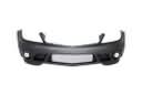
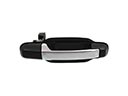
- Body & Hardware Parts View More >
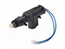
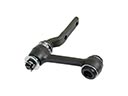
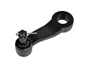
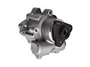
- Steering Parts View More >
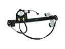
- Electrical Parts View More >
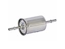
- Air & Fuel Delivery Parts View More >
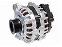
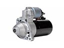
- Charging & Starting Parts View More >
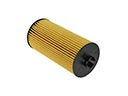
- Engine Parts View More >
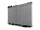
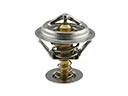
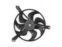
- Belts & Cooling Parts View More >
- Suspension Parts View More >
- Driveline & Axles Parts View More >
- Emission Control & Exhaust Parts View More >
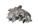
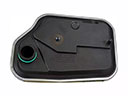
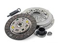
- Transmission Parts View More >
- Brakes Parts View More >
Why Buy Genuine Chevrolet Astro Parts From ChevyPartsGiant.com
Looking for real Chevrolet Astro parts? ChevyPartsGiant.com may be a better choice to find genuine parts at wallet-friendly prices. We sell only OEM Chevrolet Astro parts, ensuring perfect fit, reliability, and long-term performance. With our website, you can easily get access to the same parts found at local Chevrolet stores. All components are produced by Chevrolet and are exclusively fitted on Chevrolet Astro automobiles. By shopping at our store, you can enjoy the quality of the Chevrolet factory without the high prices of brick-and-mortar facilities. We achieve this because we are an online store operating at lower costs, which we pass on to you. We also have a user-friendly platform where you can find and order genuine Chevrolet Astro parts swiftly. We are here to make your process of restoring a Chevrolet Astro or dealing with simple repairs quick and inexpensive. We also make it easy to obtain Chevrolet Astro parts at competitive shipping prices and a team of knowledgeable staff ready to take your order. Choose ChevyPartsGiant.com to save time and money, as well as keep your Chevrolet Astro in the good condition.
Between 1985 until 2005 Chevrolet manufactured the Astro van which became famous for its strong engineering design and its capability to serve both as a passenger vehicle and a cargo transportation system. The Chevrolet Astro utilized GMT330 platform construction and offered its drivers the option of rear-wheel or all-wheel drive since 1990 to maximize road performance. The Chevrolet Astro's engine transition started with a 4.3 L V6 that delivered 165 hp at launch up to a V6 4.3 L that provided 165 hp initially followed by 190 hp and achieved 200 hp after introducing the Vortec version in 1996. The Chevrolet Astro offered manual transmission options with a five-speed Borg-Warner T-5 manual and automatic transmission with four-speed 700R4 from 1985 to 1989. A shift occurred in 1989 when General Motors eliminated the manual transmission so customers only had the automatic 700R4 (renamed 4L60) transmission to choose from until 1994. The Chevrolet Astro benefits from its 111-inch wheelbase which enhances both stability during driving and handling ability. The 1990 Chevrolet Astro received two new features that improved its part functionality - an analog dashboard combined with a hydroboost braking system. Several aesthetic updates altered the Chevrolet Astro throughout its lifetime and in 1995 the vehicle received a particularly radical change represented by a longer front section and the installation of passenger-side airbags in 1996 among other changes. The production of genuine Chevrolet Astro replacement parts remained accessible during every stage of production to let owners preserve their vehicles with parts which fulfilled original specifications and quality requirements.
Chevrolet Astro issues group into engine fuel delivery, body electrical, and transmission hydraulics. In the engine bay, the Astro may stall or fail to start. A weak fuel pump or a clogged filter drops pressure and flow. Confirm with a pressure gauge and voltage checks at the pump connector. Change the fuel pump, change filter and clean grounds. The Astro's body electrical system may have loss of window movement after a heat soak. The window might move slowly, halt midway way and regain ground after cooling. Ensure switch, check power and ground, and examine connectors to check the adjustment of the connectors to heat. Install a new window regulator motor to restore consistent operation. In the transmission, some Astro vans set code P1870 and shift harshly. Wear in the TCC valve body bores causes clutch control faults. Follow Chevrolet service procedures for torque specs, electrical checks, and TCC diagnostics. Repair requires a corrected valve body, then relearn adaptives and service fluid. After repairs, review data and verify smooth shifts on the Astro. Finish with a leak check so the Astro leaves without recurring warnings. These steps keep the Chevrolet drivetrain responsive and the Chevrolet cabin systems reliable.
Chevrolet Astro Parts and Q&A
- Q: How to replace the alternator on Chevrolet Astro?A:Disipple the air cleaner assembly, and unscrew the battery negative cable, to replace the alternator. Removal of drive belt and disconnection of the regulator electrical connector. You will have to remove the controller mounting bolts and the output terminal nut before removing the generator. Installation Replace by putting back the generator and fitting parts.
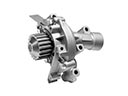
- Q: How to replace a water pump on Chevrolet Astro?A:To replace the water pump, make sure that the engine is cool, then empty the coolant. Remove the air cleaner assembly, MAF sensor and upper fan shroud. Remove the drive belt, fan assembly and coolant pump pulley. Disconnect hoses, remove pump and check parts. Install the new pump and reconnect everything, and refill the radiator and check for leaks.
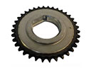
- Q: How to replace the camshaft on Chevrolet Astro?A:In order to remove the camshaft, one will have to remove the engine cover, air cleaner assembly, radiator, A/C condenser, and the grille. Removal of the valve lifters, timing chain, camshaft sprocket and balance shaft drive gear. Wipe the camshaft and bearings, and attach the new camshaft and fit up the parts.


