ChevyParts
My Garage
My Account
Cart
OEM Chevrolet Astro Wheel Bearing
Hub Bearing- Select Vehicle by Model
- Select Vehicle by VIN
Select Vehicle by Model
orMake
Model
Year
Select Vehicle by VIN
For the most accurate results, select vehicle by your VIN (Vehicle Identification Number).
12 Wheel Bearings found


Chevrolet Astro Wheel Bearing, Rear Part Number: 12479031
$49.62 MSRP: $96.32You Save: $46.70 (49%)

Chevrolet Astro Axle Bearings, Front Part Number: 457434
$10.48 MSRP: $27.74You Save: $17.26 (63%)Ships in 1-2 Business Days

Chevrolet Astro Wheel Bearing, Front Part Number: 457196
$23.04 MSRP: $43.24You Save: $20.20 (47%)Ships in 1-2 Business Days

Chevrolet Astro Wheel Bearing Part Number: 457049
$24.87 MSRP: $45.03You Save: $20.16 (45%)Ships in 1 Business Day


Chevrolet Astro Axle Bearings, Front Part Number: 26053326
$11.46 MSRP: $20.46You Save: $9.00 (44%)Ships in 1-3 Business Days


Chevrolet Astro Hub & Bearing, Front Passenger Side Part Number: 15112450
$153.49 MSRP: $288.24You Save: $134.75 (47%)Ships in 1-2 Business DaysChevrolet Astro Hub & Bearing, Front Driver Side Part Number: 15112451
$340.13 MSRP: $572.24You Save: $232.11 (41%)Ships in 1-2 Business Days
Chevrolet Astro Front Hub & Bearing Part Number: 15058393
Chevrolet Astro Hub & Bearing, Front Driver Side Part Number: 15997073
Chevrolet Astro Hub & Bearing, Front Part Number: 15693440

Chevrolet Astro Axle Bearing, Rear Part Number: 12471604
Chevrolet Astro Wheel Bearing
Want to cut long-term maintenance and repair costs? Choose OEM Wheel Bearing. Those parts deliver top durability you can trust. On our site, you'll find a huge catalog of genuine Chevrolet Astro parts. Prices are unbeatable, so you can keep more in your pocket. Every OEM Chevrolet Astro Wheel Bearing includes a manufacturer's warranty. You can also get an easy return policy that keeps buying risk free. Fast delivery, get your car on the road quickly. It's simple to search, compare, and order. Stop guessing about quality or fit. Order today and save with parts that last.
Chevrolet Astro automobiles contain a crucial component known as the Wheel Bearing which is responsible for helping the wheels turn smoothly with little the resistance. The most common fitment of these vehicles used is the unit or integral hub and bearing assembly which may incorporate an ABS sensor and is replaced as an assembly. On non-driven axle hubs some models may be equipped with replaceable tapered roller bearings for easy checking and renewal. Old or bad wheel bearings can cause such things as noise, vibration, and in the extreme a vehicle can develop the danger of a wheel coming off. It is important to carry out routine checks such as the used shaft surface roughness and play and lubrication by high temperature wheel bearing grease. This paper seeks to look at the condition of the Chevrolet Astro's wheel bearing systems which play a big part in its efficiency and safety.
Chevrolet Astro Wheel Bearing Parts and Q&A
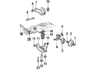
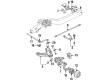
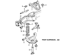
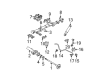
- Q: How to service and repair the front wheel bearing and hub on Chevrolet Astro?A:Before starting work on the front Wheel Bearing hub you must drain two-thirds of the brake reservoir fluid and lift the vehicle up. Put the wheel assembly aside before adding shielding over the axle joint. Hold up the brake caliper with a wire piece to safeguard the Brake Line before taking off the brake caliper and rotor unit. Pull out the speed sensor electrical plug before taking the bearing speed sensor off its position. First disconnect the drive axle nut and washer before unwinding the Tie Rod End nut from its mount on the knuckle. Remove the hub and bearing assembly with a puller then take out all drive axle and splash shield bolts to pull out the splash shield. Place the steering knuckle in a jack stand and begin disconnecting the upper Ball Joint by loosening its nut and joining the Ball Joint separator tool (J 36607). Use the Ball Joint remover j 35917 to detach the lower Ball Joint from the knuckle before unbolting them both from the corresponding assembly. To install this component efficiently you need the knuckle seal installer (J 36605). Insert the seal into the knuckle using this tool and then link the knuckle to both ball joints before installing the lower Ball Joint with its steering knuckle nut tightened to 128 nm (95 ft. Lbs.) then the upper Ball Joint with its steering knuckle nut torqued to 98 nm (72 ft. Lbs.). After servicing the joints add new cotter pins then fasten the nuts one sixteenth more to thread the pins through the joint studs. Press flat the bent end of each cotter pin against the studs. Place the splash shield properly and fasten its bolts to 16 nm (12 ft. Lbs). Position the drive axle parts into the threaded holes and tighten the bolts evenly to 90 nm (66 ft. Lbs. Force). Secure drive axle washer to its nut before installing outer tie rod and sensor components while screwing the nut to 200 nm and the speed sensor connector. End by placing the brake rotor and caliper in position then pulling off the axle joint cover before adding the tire and wheel components. Lower the vehicle and make sure to monitor the master cylinder fluid to add amount when low. You have to press the brake pedal until it feels firm, inspect the brake fluid again, check the front wheel alignment and measure vehicle trim height prior to taking the vehicle for a test drive.
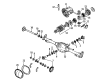
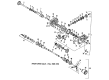
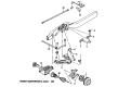
- Q: How to replace the rear axle wheel bearing and wheel seal on Chevrolet Astro?A:The process of replacing rear Axle Shaft seals or bearings starts by elevating the vehicle and then removing tires and wheels and the housing cover of the rear axle. First remove the Axle Shaft before extracting the Axle Shaft seal and bearing from the housing through the use of rear axle seal and bearing remover (J 44685) and slide hammer (J 2619-01). To install the Axle Shaft bearing use the bearing installer (J 34794) together with the universal driver handle (J 8092) until the tool meets the tube. For installation of the Axle Shaft seal employ the Axle Shaft seal installer (J 23771) to drive the seal until it reaches tube flushness. Continue with the reinstall process by placing back the Axle Shaft followed by the rear axle housing cover and tire and wheel assembly. Put the suitable fluid into the rear axle before lowering the vehicle.


Related Chevrolet Astro Parts
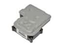 Chevrolet Astro ABS Control Module
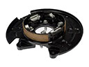 Chevrolet Astro Brake Backing Plate
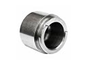 Chevrolet Astro Brake Caliper Piston
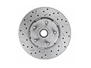 Chevrolet Astro Brake Disc
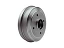 Chevrolet Astro Brake Drum
 Chevrolet Astro Brake Line
 Chevrolet Astro Brake Pad
 Chevrolet Astro Brake Proportioning Valve
 Chevrolet Astro Parking Brake Shoe
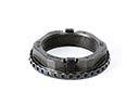 Chevrolet Astro Spindle Nut
 Chevrolet Astro Wheel Bearing Dust Cap
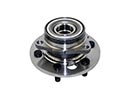 Chevrolet Astro Wheel Hub