ChevyParts
My Garage
My Account
Cart
OEM 2001 Chevrolet Corvette Front Cross-Member
Front Engine Cross Member- Select Vehicle by Model
- Select Vehicle by VIN
Select Vehicle by Model
orMake
Model
Year
Select Vehicle by VIN
For the most accurate results, select vehicle by your VIN (Vehicle Identification Number).
1 Front Cross-Member found

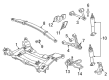
2001 Chevrolet Corvette Engine Cradle Part Number: 10319530
Product Specifications- Other Name: Crossmember; Crossmember, Front Frame Cross Member
- Position: Front
- Replaces: 10266822, 10312076
- Item Weight: 38.10 Pounds
- Item Dimensions: 39.5 x 26.0 x 8.2 inches
- Condition: New
- Fitment Type: Direct Replacement
- SKU: 10319530
- Warranty: This genuine part is guaranteed by GM's factory warranty.
2001 Chevrolet Corvette Front Cross-Member
With a comprehensive array of OEM 2001 Chevrolet Corvette Front Cross-Member, from fuel pumps to door handles, our website is a one-stop-shop for your needs. All our genuine 2001 Chevrolet Corvette Front Cross-Member are backed by the manufacturer's warranty and are offered at competitive prices in the market. Rest assured, you can shop with complete confidence.
2001 Chevrolet Corvette Front Cross-Member Parts Questions & Experts Answers
- Q: How to replace the Front Cross-Member on 2001 Chevrolet Corvette?A: Removing the front suspension crossmember commencement, start by removing the generator from the accessory mounting bracket while removing the washer pump/reservoir. Next, unplug the engine coolant temperature switch electrical connector and the front headlamp electrical connector. Support the engine with the j 41803 (Engine Support Fixture) and j 28467-b (Universal Engine Support Fixture) and then raise and support the vehicle. Perform the following: remove the tire and wheel assemblies, followed by the outer Tie Rod End stud nuts on the steering linkage. Remove the Shock Absorber solenoid power connector if equipped and the real time damping (RTD) sensor connections. Take off the stabilizer shaft, unbolt electronic brake control module/brake pressure modulator valve (EBCM/BPMV) bracket bolts from the crossmember, secure the ebcm/bpmv away from the crossmember. Take the power steering gear mounting bolts and power steering fluid cooler off, then take the power steering gear off the crossmember. The j 33432-a is a (Transverse Spring Compressor) that should be used to take away the transverse spring from the vehicle, then take off the lower shock absorbert bolts, and take away from the low control arm bolts from the cross member. Set a transmission jack underneath the crossmember, unbolt the engine mount (low), and take the wheel speed sensor wire harness, electrical, brake pipe from the crossmember. Last, unbolt the cross member mounting nuts and un-bolt the crossmember from the car. To install, lift back the crossmember and align dowel pins and engine mount studs then insert new nuts for crossmember and fasten them to a torque of 110 nm (81 ft. Lbs.). Replace the engine mount lower nuts, secure the wheel speed sensor wiring harness, brake pipe, and electrical harness on the crossmember and install the transverse spring, with the j 33432-a part, reconnect the lower control arm, the shock absorbers, and power steering gear, screw the bolts to 28 nm (21 ft. Lbs.) and 100 nm (74 ft. Lbs.); accordingly. Reinstall the brake pressure modulator valve bracket bolt and connect the intermediate shaft to the steering gear, fasten the steering linkage outer tie rod ends. Reconnect the rtd sensor links, shock absorber solenoid electrical connector and install stabilizer shaft, and tire and wheel assemblies. Lower the vehicle, remove the j 41803 and j 28467-b from the engine, and reinstall the generator and washer pump/reservoir. Lastly, connect the engine coolant temperature switch electrical connector, front headlamp electrical connector, and negative Battery Cable, tightening it to 15 nm (11 ft. Lbs.), and undergo vehicle front end alignment.