ChevyParts
My Garage
My Account
Cart
OEM 2001 Chevrolet Tracker Intake Manifold
Engine Intake Manifold- Select Vehicle by Model
- Select Vehicle by VIN
Select Vehicle by Model
orMake
Model
Year
Select Vehicle by VIN
For the most accurate results, select vehicle by your VIN (Vehicle Identification Number).
2 Intake Manifolds found
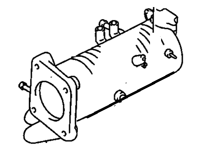
2001 Chevrolet Tracker Intake Manifold Part Number: 91176126
Product Specifications- Other Name: Manifold, Intake
- Item Weight: 9.40 Pounds
- Item Dimensions: 17.5 x 13.1 x 9.9 inches
- Condition: New
- SKU: 91176126
- Warranty: This genuine part is guaranteed by GM's factory warranty.
2001 Chevrolet Tracker Intake Manifold Part Number: 91176128
Product Specifications- Other Name: Manifold
- Condition: New
- SKU: 91176128
- Warranty: This genuine part is guaranteed by GM's factory warranty.
2001 Chevrolet Tracker Intake Manifold
With a comprehensive array of OEM 2001 Chevrolet Tracker Intake Manifold, from fuel pumps to door handles, our website is a one-stop-shop for your needs. All our genuine 2001 Chevrolet Tracker Intake Manifold are backed by the manufacturer's warranty and are offered at competitive prices in the market. Rest assured, you can shop with complete confidence.
2001 Chevrolet Tracker Intake Manifold Parts Questions & Experts Answers
- Q: How to service and repair the intake manifold on 2001 Chevrolet Tracker?A: Service and repair of the Intake Manifold starts with removing the fuel tank filler cap to reduce fuel vapor pressure before reinstalling it. Remove fuel pressure while you disconnect the negative cable from the battery. Remove the vehicle's cooling system liquid while also detaching both the mass air flow (MAF) sensor and intake air temperature (IAT) sensor. First disconnect the air cleaner assembly electrical harness clamps while detaching the air intake hose that connects to the Throttle Body. The repair requires detachment of the accelerator cable from its bracket location and its position on the bellcrank portion of the Throttle Body. The service requires removal of the throttle position (TP) sensor along with the idle air control (IAC) valve and engine coolant temperature (ECT) sensor and evaporative emission canister purge valve. Squeeze together the bracket and valve assembly by removing the evap canister purge valve vacuum hose and its bracket bolt. Then pull out the bracket and valve assembly. The coolant hose removal from the Throttle Body requires disconnecting of the exhaust gas recirculation (EGR) connector and the manifold absolute pressure (MAP) sensor connector and engine ground wire from the Intake Manifold. Disconnect the brake booster supply hose from its position on the Intake Manifold by placing a shop rag under the hose to collect any fuel that may leak from disrupted fuel lines. Disrupt the fuel lines connecting both inlet and return before you remove the upper Radiator Hose from its Thermostat Housing placement. The procedure requires removal of the upper generator mounting bracket as well as the lower Intake Manifold support bracket from the Intake Manifold. Take out the upper front Intake Manifold support bracket along with the upper rear Intake Manifold support bracket from the Intake Manifold. Extract both the crankcase vent hose and the pcv hose from their positions on the PCV Valve. Start by disconnecting the fuel injector 6-way connector at the rear of the Intake Manifold before you remove the EGR Valve along with all eight nuts, three bolts, and the Intake Manifold and gasket binding the Cylinder Head. Transfer the ect sensor, ect sensor sending unit, throttle body, fuel rail, fuel injector harness, map sensor, egr tube and accelerator cable bracket according to required steps. During assembly place the EGR Valve and ect sensor and ect sensor sending unit and Throttle Body and Fuel Rail and fuel injector harness and map sensor and EGR Tube and accelerator cable bracket onto the Intake Manifold. Double check all connections before using new Intake Manifold gaskets to mount the Intake Manifold to the Cylinder Head using 8 nuts and 3 bolts torque to 23 nm (17 ft. Lbs.). The upper rear Intake Manifold support bracket gets installed through two bolts that require 50 nm (37 ft. Lbs. Of torque), while the upper front Intake Manifold support bracket needs the same torque using 2 bolts. Affix the crankcase vent hose and pcv hose onto the pv valve. The 6-way connector of the fuel injector should be connected at the Intake Manifold rear while installing the lower Intake Manifold support bracket through 2 bolts that need tightening at 50 nm (37 ft. Lbs.). Failure to tighten the two upper bracket bolts to 50 nm (37 ft. Lbs.) can lead to exceeding the upper torque limit. Adjust the generator drive belt tension after bolting up the bracket. Reinstall the evap canister followed by connecting the upper Radiator Hose onto the Thermostat Housing . Affix fuel inlet hose and return hose to their positioning on the fuel line union. The service must begin with reconnecting the egr connector and map sensor connector and engine ground wire to the Intake Manifold followed by reconnecting the brake booster supply hose. After installing all components the evap canister purge valve vacuum hose must be placed before continuing with the procedure. First connect the Throttle Body coolant hose before installing both the accelerator cable and Throttle Body bellcrank to its respective mounting positions. Make all necessary adjustments during installation. When finished install the electrical harness clamps onto the air cleaner assembly while also connecting the iat sensor and maf sensor to the Throttle Body. Then perform cooling system refilling as needed before tightening the negative Battery Cable bolt to 15 nm (11 ft. Lbs.).


