ChevyParts
My Garage
My Account
Cart
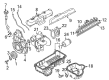
OEM 2002 Chevrolet Astro Intake Manifold
Engine Intake Manifold- Select Vehicle by Model
- Select Vehicle by VIN
Select Vehicle by Model
orMake
Model
Year
Select Vehicle by VIN
For the most accurate results, select vehicle by your VIN (Vehicle Identification Number).
2 Intake Manifolds found


2002 Chevrolet Astro Intake Manifold Part Number: 17113542
Product Specifications- Other Name: Manifold Kit, Engine Fuel Intake Manifold; Manifold
- Position: Upper
- Replaces: 17113213
- Item Weight: 3.30 Pounds
- Item Dimensions: 7.4 x 13.5 x 12.5 inches
- Condition: New
- Fitment Type: Direct Replacement
- SKU: 17113542
- Warranty: This genuine part is guaranteed by GM's factory warranty.
2002 Chevrolet Astro Intake Manifold, Lower Part Number: 88894294
Product Specifications- Other Name: Manifold Kit, Lower Intake; Manifold; Manifold Kit, Engine Fuel Intake Manifold
- Position: Lower
- Item Weight: 19.50 Pounds
- Item Dimensions: 21.7 x 17.8 x 15.2 inches
- Condition: New
- Fitment Type: Direct Replacement
- SKU: 88894294
- Warranty: This genuine part is guaranteed by GM's factory warranty.
2002 Chevrolet Astro Intake Manifold
With a comprehensive array of OEM 2002 Chevrolet Astro Intake Manifold, from fuel pumps to door handles, our website is a one-stop-shop for your needs. All our genuine 2002 Chevrolet Astro Intake Manifold are backed by the manufacturer's warranty and are offered at competitive prices in the market. Rest assured, you can shop with complete confidence.
2002 Chevrolet Astro Intake Manifold Parts and Q&A
- Q: How to replace the upper intake manifold on 2002 Chevrolet Astro?A: Start the process of replacing the upper Intake Manifold by removing the engine cover and the air cleaner outlet duct from the Throttle Body. Remove the accelerator control cable and the cruise control cable, if applicable, from the throttle shaft and the accelerator control cable bracket. Allowing the PCV Valve Hose assembly to go first from the Intake Manifold and from the valve rockerarm cover, followed by the nut that retains the a/c hose bracket, if so equipped, to the Intake Manifold stud, and remove the a/c hose bracket. Next, unscrew the nut holding the engine wiring harness bracket to the Intake Manifold stud and disconnect the electrical connectors for both the a/c compressor clutch and a/c high pressure cutoff switch , also disconnect the electrical connectors for the throttle position (TP) sensor, idle air control (IAC), motor, car feul meter body assembly connector, manifold absolute pressure (MAP), and the evap canister purge solenoid valve. Pulls the engine wire harness aside and unclips the evap canister purge valve and unclip the vacuum hose from the Intake Manifold. It is important to remove the bolt attaching the transmission fluid filler tube to the accelerator control cable bracket and remove the accelerator control cable bracket from the Throttle Body and the Intake Manifold. Take out the fuel lines from the fuel meter body assembly, followed by the studs for upper Intake Manifold and upper Intake Manifold. Needless to say, eliminate the gasket of the upper Intake Manifold and the fuel meter, while protect them from soaking into cleaning solvent. Clean all sealing areas and inside the upper Intake Manifold, viewing for cracks, damages, or loose of bolt hole thread inserts. The upper Intake Manifold needs replacement, take off the pcv valve cover discarding the seal and reinstall the Throttle Body and MAP Sensor of they have been removed. Replace a new seal (O-ring) on the pcv valve cover and lubricate with clean engine oil, and tighten it at the upper intemal manifold. Apply a new seal to the body of fuel meter assembly, lubricate then place a new upper Intake Manifold to lower Intake Manifold gasket to groove of an upper Intake Manifold before setting an upper Intake Manifold to the lower Intake Manifold. In the event that used fasteners are used then engage threads of the upper Intake Manifold attaching bolts with the threadlock gm p/n 12345382 or equivalent before installing the upper Intake Manifold attaching studs, which should be tightened to 5 nm (44 inch lbs.) before final tightening up to 9 nm (80 inch lbs.). Reconnect the fuel lines to the fuel meter body assembly, re-secure the evap canister purge valve, and reconnect the accelerator control cable bracket, studs, and nuts to the Intake Manifold and Throttle Body, tightening it to 12 nm (106 inch lbs.). Clip hose to Intake Manifold, reattach trans filltube and bolt to accel cable bracket 6 nm (53 inch lbs.). Connect the engine wiring harness and then reconnect the electrical connectors for the a/c compressor clutch , a/c high pressure cutoff switch , throttle position (TP) sensor , idle air control (IAC) motor , fuel meter body assembly connector , map sensor , and evap canister purge solenoid valve . Position the engine wiring harness bracket and nut onto the Intake Manifold stud, which needs to be tightened to 12 nm (106 inch lbs.), then with the a/c hose bracket and nut, if available, to the Intake Manifold stud at 5 nm (44 inch lbs.), and the other engine wiring harness bracket and nut onto the stud at the evap canister purge solenoid valve, while tightening it to 8 nm (71inch lbs.). Last but not least, reconnect PCV Valve Hose assembly to the Intake Manifold and valve rocker arm cover, reconnect the cruise control cable if equipped, attach accelerator control cable, and follow up with securing air cleaner outlet duct to the Throttle Body assembly and finally engine cover.
Related 2002 Chevrolet Astro Parts
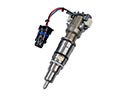 2002 Chevrolet Astro Fuel Injector
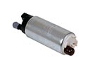 2002 Chevrolet Astro Fuel Pump
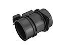 2002 Chevrolet Astro Mass Air Flow Sensor
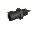 2002 Chevrolet Astro Air Charge Temperature Sensor
 2002 Chevrolet Astro Air Filter
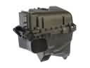 2002 Chevrolet Astro Air Filter Box
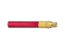 2002 Chevrolet Astro Air Hose
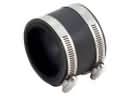 2002 Chevrolet Astro Air Intake Coupling
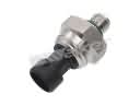 2002 Chevrolet Astro Fuel Pressure Sensor
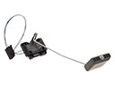 2002 Chevrolet Astro Fuel Tank Sending Unit
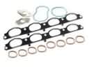 2002 Chevrolet Astro Intake Manifold Gasket
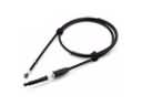 2002 Chevrolet Astro Throttle Cable