ChevyParts
My Garage
My Account
Cart
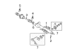
OEM 2006 Chevrolet Malibu Steering Angle Sensor
Steering Column Angle Position Sensor- Select Vehicle by Model
- Select Vehicle by VIN
Select Vehicle by Model
orMake
Model
Year
Select Vehicle by VIN
For the most accurate results, select vehicle by your VIN (Vehicle Identification Number).
1 Steering Angle Sensor found


2006 Chevrolet Malibu Position Sensor Part Number: 15260309
$112.18 MSRP: $192.65You Save: $80.47 (42%)Ships in 1-2 Business DaysProduct Specifications- Other Name: Sensor, Steering Column; Steering Wheel Speed Sensor
- Item Weight: 0.40 Pounds
- Item Dimensions: 5.2 x 4.2 x 4.2 inches
- Condition: New
- Fitment Type: Direct Replacement
- SKU: 15260309
- Warranty: This genuine part is guaranteed by GM's factory warranty.
2006 Chevrolet Malibu Steering Angle Sensor
With a comprehensive array of OEM 2006 Chevrolet Malibu Steering Angle Sensor, from fuel pumps to door handles, our website is a one-stop-shop for your needs. All our genuine 2006 Chevrolet Malibu Steering Angle Sensor are backed by the manufacturer's warranty and are offered at competitive prices in the market. Rest assured, you can shop with complete confidence.
2006 Chevrolet Malibu Steering Angle Sensor Parts Questions & Experts Answers
- Q: How to center the Steering Angle Sensor on 2006 Chevrolet Malibu?A: Customers need to recognize the sensor type by using provided illustration images before removing it. The sensor connector's FRONT end faces the right side of the transaxle. No sensor centering is necessary before removal when using existing equipment again. Separate the sensor connector then extract the sensor by removing it from the adapter and bearing assembly. An alignment mark should be made on the flush rotor flange cuff before sensor removal to avoid install time misalignment issues. The sensor installation requires a front-facing foam ring together with a pin hole for the centering pin and the front rotor flange cuff to be level with the surface. New sensors arrive with a pin which must stay in position until the sensor reaches its correct placement. Install the sensor by aligning it to the steering shaft afterwards slot it into the adapter and bearing assembly before connecting its components. A pin slot faces the FRONT of the sensor and pairs with a centering pin while a rotor flange cuff maintains flush contact. Four foam rings complete this configuration. An alignment mark rounds out the sensor features at the FRONT. The BACK side of the sensor incorporates double D flats along with a foam ring while carrying an alignment tab. When using an existing sensor make sure to line up the marks on the flush rotor flange cuff before adding it into position. For brand new sensors follow the same installation steps while maintaining pin contact until the sensor reaches its installed position. The sensor front reveals a pin hole beside a raised rotor flange cuff along with an alignment mark. The BACK shows two major flat areas with an alignment indicator. All installation procedures must cover all sensor types including careful alignment steps until both connection points are secure.