ChevyParts
My Garage
My Account
Cart
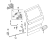
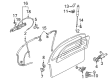
OEM 2006 Chevrolet Uplander Door Handle
Inside Door Handle- Select Vehicle by Model
- Select Vehicle by VIN
Select Vehicle by Model
orMake
Model
Year
Select Vehicle by VIN
For the most accurate results, select vehicle by your VIN (Vehicle Identification Number).
25 Door Handles found


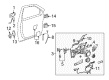
2006 Chevrolet Uplander Handle, Inside Part Number: 89044625
$126.25 MSRP: $188.75You Save: $62.50 (34%)Ships in 1-3 Business DaysProduct Specifications- Other Name: Handle, Door Lock Remote Control Inside; Interior Door Handle
- Position: Front Driver Side
- Item Weight: 0.40 Pounds
- Item Dimensions: 5.6 x 3.4 x 2.1 inches
- Condition: New
- Fitment Type: Direct Replacement
- SKU: 89044625
- Warranty: This genuine part is guaranteed by GM's factory warranty.


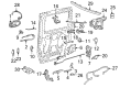
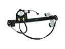
2006 Chevrolet Uplander Handle, Outside, Driver Side Part Number: 10322223
$207.07 MSRP: $309.58You Save: $102.51 (34%)Ships in 1-2 Business DaysProduct Specifications- Other Name: Handle, Door Outside Handle; Exterior Door Handle
- Position: Driver Side
- Replaces: 10298454, 10280414
- Item Weight: 1.30 Pounds
- Item Dimensions: 5.2 x 5.3 x 11.3 inches
- Condition: New
- Fitment Type: Direct Replacement
- SKU: 10322223
- Warranty: This genuine part is guaranteed by GM's factory warranty.

2006 Chevrolet Uplander Handle, Outside, Driver Side Part Number: 15105126
$40.31 MSRP: $57.68You Save: $17.37 (31%)Product Specifications- Other Name: Handle, Door Outside Handle; Exterior Door Handle
- Position: Driver Side
- Item Weight: 1.00 Pounds
- Item Dimensions: 9.2 x 4.5 x 3.4 inches
- Condition: New
- Fitment Type: Direct Replacement
- SKU: 15105126
- Warranty: This genuine part is guaranteed by GM's factory warranty.
2006 Chevrolet Uplander Handle, Outside, Passenger Side Part Number: 10322222
$160.87 MSRP: $232.18You Save: $71.31 (31%)Ships in 1-2 Business DaysProduct Specifications- Other Name: Handle, Door Outside Handle; Exterior Door Handle
- Position: Passenger Side
- Replaces: 10298455, 10280415
- Item Weight: 1.30 Pounds
- Item Dimensions: 5.2 x 5.2 x 11.1 inches
- Condition: New
- Fitment Type: Direct Replacement
- SKU: 10322222
- Warranty: This genuine part is guaranteed by GM's factory warranty.

2006 Chevrolet Uplander Handle, Outside Part Number: 10322225
$8.81 MSRP: $13.12You Save: $4.31 (33%)Ships in 1-3 Business DaysProduct Specifications- Other Name: Handle, Door Outside Handle; Exterior Door Handle
- Position: Rear
- Replaces: 10333953, 10324099, 10322241, 10404749, 10404745, 10404751, 15146528, 15138024, 15928720, 15928724, 15928727, 10404755, 10333957, 10333955, 10404753, 10404735, 15105105, 15138029, 15146530, 15138019
- Item Weight: 1.30 Pounds
- Item Dimensions: 5.2 x 5.2 x 10.6 inches
- Condition: New
- Fitment Type: Direct Replacement
- SKU: 10322225
- Warranty: This genuine part is guaranteed by GM's factory warranty.

2006 Chevrolet Uplander Handle, Outside, Black, Front Driver Side Part Number: 10322201
$42.59 MSRP: $63.40You Save: $20.81 (33%)Ships in 1-2 Business DaysProduct Specifications- Other Name: Handle Assembly-Front Side Door Outside *Black; Exterior Door Handle; Handle, Door Outside Handle
- Position: Front Driver Side
- Replaces: 10298451, 10271406
- Item Weight: 0.90 Pounds
- Item Dimensions: 12.0 x 6.6 x 4.4 inches
- Condition: New
- Fitment Type: Direct Replacement
- SKU: 10322201
- Warranty: This genuine part is guaranteed by GM's factory warranty.

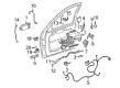
2006 Chevrolet Uplander Handle, Outside, Passenger Side Part Number: 19257094
$36.05 MSRP: $68.77You Save: $32.72 (48%)Product Specifications- Other Name: Handle, Door Outside Handle; Exterior Door Handle
- Position: Passenger Side
- Replaces: 10341850, 15138021, 10341848, 10344003
- Item Weight: 0.90 Pounds
- Item Dimensions: 9.2 x 4.8 x 4.0 inches
- Condition: New
- Fitment Type: Direct Replacement
- SKU: 19257094
- Warranty: This genuine part is guaranteed by GM's factory warranty.


2006 Chevrolet Uplander Handle, Inside Part Number: 15222933
Product Specifications- Other Name: Handle, Door Lock Inside Handle; Interior Door Handle; Handle; Handle, Door Lock Remote Control Inside
- Position: Rear
- Item Weight: 0.50 Pounds
- Item Dimensions: 6.3 x 4.2 x 4.2 inches
- Condition: New
- Fitment Type: Direct Replacement
- SKU: 15222933
- Warranty: This genuine part is guaranteed by GM's factory warranty.
- Product Specifications
- Other Name: Exterior Door Handle
- Position: Driver Side
- Item Weight: 0.90 Pounds
- Item Dimensions: 9.1 x 4.3 x 3.4 inches
- Condition: New
- SKU: 15138027
- Warranty: This genuine part is guaranteed by GM's factory warranty.
- Product Specifications
- Other Name: Handle Assembly-Front Side Door Outside *Emerald Jewe; Exterior Door Handle
- Position: Passenger Side
- Item Weight: 0.90 Pounds
- Item Dimensions: 9.2 x 4.7 x 4.0 inches
- Condition: New
- SKU: 15105127
- Warranty: This genuine part is guaranteed by GM's factory warranty.
- Product Specifications
- Other Name: Exterior Door Handle
- Position: Passenger Side
- Item Weight: 0.90 Pounds
- Item Dimensions: 11.9 x 6.3 x 4.2 inches
- Condition: New
- SKU: 15138026
- Warranty: This genuine part is guaranteed by GM's factory warranty.
- Product Specifications
- Other Name: Handle Assembly-Front Side Door Outside *Blue; Exterior Door Handle
- Position: Front Passenger Side
- Item Weight: 0.90 Pounds
- Item Dimensions: 9.1 x 4.7 x 3.9 inches
- Condition: New
- SKU: 15146526
- Warranty: This genuine part is guaranteed by GM's factory warranty.
- Product Specifications
- Other Name: Handle, Door Outside Handle; Exterior Door Handle
- Position: Passenger Side
- Item Weight: 0.90 Pounds
- Item Dimensions: 9.3 x 4.7 x 4.0 inches
- Condition: New
- Fitment Type: Direct Replacement
- SKU: 15146525
- Warranty: This genuine part is guaranteed by GM's factory warranty.
- Product Specifications
- Other Name: Handle Assembly-Front Side Door Outside *Red D; Exterior Door Handle
- Position: Driver Side
- Item Weight: 1.10 Pounds
- Item Dimensions: 9.2 x 4.5 x 3.4 inches
- Condition: New
- SKU: 15138022
- Warranty: This genuine part is guaranteed by GM's factory warranty.

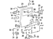
2006 Chevrolet Uplander Handle, Outside, Black Part Number: 15850461
Product Specifications- Other Name: Handle Assembly-Lift Gate Outside *Black; Tailgate Handle; Handle, Rear Compartment Lid Or Tail Gate Latch; Handle, End Gate Lock
- Replaces: 15175953, 15782405
- Item Weight: 1.30 Pounds
- Item Dimensions: 9.4 x 9.4 x 29.1 inches
- Condition: New
- Fitment Type: Direct Replacement
- SKU: 15850461
- Warranty: This genuine part is guaranteed by GM's factory warranty.
2006 Chevrolet Uplander Handle, Inside Part Number: 89044624
Product Specifications- Other Name: Handle, Door Lock Remote Control Inside; Interior Door Handle
- Position: Front Passenger Side
- Item Weight: 0.40 Pounds
- Item Dimensions: 6.1 x 4.2 x 4.1 inches
- Condition: New
- Fitment Type: Direct Replacement
- SKU: 89044624
- Warranty: This genuine part is guaranteed by GM's factory warranty.

 Product Specifications
- Other Name: Handle, Assist Handle
- Position: Driver Side
- Item Weight: 0.80 Pounds
- Item Dimensions: 8.5 x 5.8 x 2.9 inches
- Condition: New
- Fitment Type: Direct Replacement
- SKU: 10365687
- Warranty: This genuine part is guaranteed by GM's factory warranty.
- Product Specifications
- Other Name: Handle, Assist Handle
- Position: Driver Side
- Item Weight: 1.00 Pounds
- Item Dimensions: 8.5 x 5.7 x 2.9 inches
- Condition: New
- Fitment Type: Direct Replacement
- SKU: 10365688
- Warranty: This genuine part is guaranteed by GM's factory warranty.
- Product Specifications
- Other Name: Handle, Assist Handle
- Position: Passenger Side
- Item Weight: 0.90 Pounds
- Item Dimensions: 8.2 x 5.4 x 1.5 inches
- Condition: New
- Fitment Type: Direct Replacement
- SKU: 10365689
- Warranty: This genuine part is guaranteed by GM's factory warranty.
- Product Specifications
- Other Name: Handle, Assist Handle
- Position: Passenger Side
- Item Weight: 0.90 Pounds
- Item Dimensions: 8.2 x 5.6 x 1.5 inches
- Condition: New
- Fitment Type: Direct Replacement
- SKU: 10365694
- Warranty: This genuine part is guaranteed by GM's factory warranty.
| Page 1 of 2 |Next >
1-20 of 25 Results
2006 Chevrolet Uplander Door Handle
With a comprehensive array of OEM 2006 Chevrolet Uplander Door Handle, from fuel pumps to door handles, our website is a one-stop-shop for your needs. All our genuine 2006 Chevrolet Uplander Door Handle are backed by the manufacturer's warranty and are offered at competitive prices in the market. Rest assured, you can shop with complete confidence.
2006 Chevrolet Uplander Door Handle Parts and Q&A
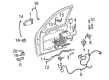
- Q: How to replace the outer sliding door handle on 2006 Chevrolet Uplander?A: The first step to remove and replace the sliding door outside handle requires the PSD 15A fuse extraction from the instrument panel fuse block to cut power for both LH and RH power sliding door modules. The first step involves taking out the sliding door inner trim panel after which professionals remove the sliding door water deflector before handling the door lock module. The barrel nut components must be removed from the lock assembly before pushing the lock rod away from the sliding door lock assembly. When equipped with the door lock module harness connector the technician should disconnect it before proceeding to remove sliding door handle screws and the lock assembly from the sliding door. First remove the outside handle cable from the lock assembly and then take out the outside handle connecting bolts from the sliding door before disconnecting the outside handle from this component. Remove the outside handle cable from the outside handle in the following step. The first step of installation requires users to connect the outside handle cable to both the outside handle and sliding door outside handle before mounting the sliding door outside handle onto the sliding door. Follow this procedure to mount the sliding door outside handle bolts while tightening them to 10 N.m (89 lb in) in their specified order before joining the outside handle cable with the lock assembly. Replace the lock assembly onto the sliding door while also tightening the sliding door handle lock actuator screws to 10 N.m (89 lb in). Complete the procedure by connecting the sliding door lock module harness connector followed by pushing the lock rod to the sliding door lock assembly then snap the barrel nut into place. The door lock module installation is complete when the control rods are connected to the sliding door outside handle with proper lock rod movement inspection. The water deflector for the sliding door and inner panel of the sliding door should be installed next. The PSD systems will become operational but require position learning of full opening and closing steps after replacing the 15A fuse into the block for restored logic power supplies.
Related 2006 Chevrolet Uplander Parts
 2006 Chevrolet Uplander Window Regulator
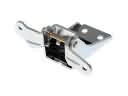 2006 Chevrolet Uplander Door Hinge
 2006 Chevrolet Uplander Door Latch Assembly
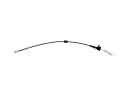 2006 Chevrolet Uplander Door Latch Cable
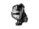 2006 Chevrolet Uplander Door Lock
 2006 Chevrolet Uplander Door Lock Actuator
 2006 Chevrolet Uplander Door Lock Cylinder
 2006 Chevrolet Uplander Door Striker
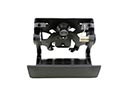 2006 Chevrolet Uplander Tailgate Handle
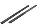 2006 Chevrolet Uplander Weather Strip
 2006 Chevrolet Uplander Window Channel
 2006 Chevrolet Uplander Window Motor