ChevyParts
My Garage
My Account
Cart
OEM Cadillac Escalade Pushrod
Valve Push Rod- Select Vehicle by Model
- Select Vehicle by VIN
Select Vehicle by Model
orMake
Model
Year
Select Vehicle by VIN
For the most accurate results, select vehicle by your VIN (Vehicle Identification Number).
3 Pushrods found


Cadillac Escalade Push Rods Part Number: 10241740
$15.16 MSRP: $23.75You Save: $8.59 (37%)Ships in 1-3 Business Days


Cadillac Escalade Push Rods Part Number: 10238852
$18.77 MSRP: $30.90You Save: $12.13 (40%)Ships in 1-2 Business Days

Cadillac Escalade Push Rods Part Number: 12619828
$3.87 MSRP: $9.12You Save: $5.25 (58%)Ships in 1-2 Business Days
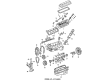
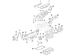
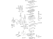
Cadillac Escalade Pushrod
Want to cut long-term maintenance and repair costs? Choose OEM Pushrod. Those parts deliver top durability you can trust. On our site, you'll find a huge catalog of genuine Cadillac Escalade parts. Prices are unbeatable, so you can keep more in your pocket. Every OEM Cadillac Escalade Pushrod includes a manufacturer's warranty. You can also get an easy return policy that keeps buying risk free. Fast delivery, get your car on the road quickly. It's simple to search, compare, and order. Stop guessing about quality or fit. Order today and save with parts that last.
Cadillac Escalade Pushrod Parts and Q&A
- Q: How to Service and Replace the Pushrod on a Cadillac Escalade?A:Before proceeding with valve Rocker Arm and push rod replacement you must remove the Rocker Arm cover. The correct engine firing pattern starts with numbers 1 and 8 then progress to 7 and 2 subsequently followed by 6 and 5 and 4 and 3 ending with numbers 1 and 3. The left-bank consists of cylinders 1, 3, 5, and 7. Start by removing the number one cylinder Spark Plug then arrange all rocker arms with pushrods and pivot support on a rack for their subsequent original installation. Begin the process by taking off each Rocker Arm bolt and continuing with the rocker arms behind it and finally the Rocker Arm pivot support and pushrods. The rocker arms alongside pushrods require cleaning and inspection according to need. The reinstallation process requires passengers to apply clean engine oil to both rocker arms and pushrods as well as to lubricate the flange portion of the Rocker Arm bolts. Install the Rocker Arm pivot support by verifying valve lifter sockets receive the pushrods correctly before fitting pushrods into the Rocker Arm ends without bolt torque yet. Follow engine firing sequence when installing the rocker arms and bolts. After turning the Crankshaft to place the number one Piston at tdc compression, verify that all number one cylinder rocker arms are in a lobe lift position. The appropriate torque for the exhaust valve bolts of cylinders 1, 2, 7, and 8 should be set to 30 n.m (22 lb ft) while the intake valve bolts of cylinders 1, 3, 4, and 5 require 30 n.m (22 lb ft). The Rocker Arm bolts guiding exhaust valves for cylinders 3, 4, 5, 6 as well as those leading intake valves for cylinders 2, 6 7, 8 require 30 n.m (22 lb ft) of torque while the Crankshaft rotates 360 degrees. Finish the installation by placing back the number one cylinder Spark Plug together with the Rocker Arm cover.

Related Cadillac Escalade Parts
 Cadillac Escalade Coolant Filter
 Cadillac Escalade Crankshaft
 Cadillac Escalade Cylinder Head
 Cadillac Escalade Oil Filler Cap
 Cadillac Escalade Oil Pan
 Cadillac Escalade Oil Pan Baffle
 Cadillac Escalade Timing Belt
 Cadillac Escalade Timing Chain Guide
 Cadillac Escalade Timing Cover
 Cadillac Escalade Timing Cover Gasket
 Cadillac Escalade Valve Cover Gasket
 Cadillac Escalade Valve Stem Oil Seal