ChevyParts
My Garage
My Account
Cart
OEM Chevrolet Silverado 3500 Classic Harmonic Balancer
Engine Harmonic Balancer- Select Vehicle by Model
- Select Vehicle by VIN
Select Vehicle by Model
orMake
Model
Year
Select Vehicle by VIN
For the most accurate results, select vehicle by your VIN (Vehicle Identification Number).
3 Harmonic Balancers found

Chevrolet Silverado 3500 Classic Vibration Damper Part Number: 97374383
$809.93 MSRP: $1280.12You Save: $470.19 (37%)Ships in 1-3 Business Days
Chevrolet Silverado 3500 Classic Vibration Damper Part Number: 12552283
$221.35 MSRP: $376.87You Save: $155.52 (42%)Ships in 1-2 Business Days


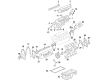
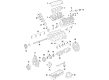
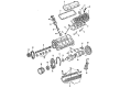
Chevrolet Silverado 3500 Classic Harmonic Balancer
Want to cut long-term maintenance and repair costs? Choose OEM Harmonic Balancer. Those parts deliver top durability you can trust. On our site, you'll find a huge catalog of genuine Chevrolet Silverado 3500 Classic parts. Prices are unbeatable, so you can keep more in your pocket. Every OEM Chevrolet Silverado 3500 Classic Harmonic Balancer includes a manufacturer's warranty. You can also get an easy return policy that keeps buying risk free. Fast delivery, get your car on the road quickly. It's simple to search, compare, and order. Stop guessing about quality or fit. Order today and save with parts that last.
Chevrolet Silverado 3500 Classic Harmonic Balancer Parts and Q&A
- Q: How to replace the Harmonic Balancer on 4.8L, 5.3L, and 6.0L engines on Chevrolet Silverado 3500 Classic?A:The replacement process for crankshaft balancer requires professionals to use these specific tools: crankshaft front oil seal installer (J 41478), crankshaft balancer and sprocket installer (J 41665), crankshaft balancer remover (J 41816), crankshaft end protector (J 41816-2), and flywheel holding tool (J 42386-A) along with angle meter (J 45059). The first step begins by taking off the air conditioning Drive Belt together with lower fan shroud and Starter motor. Use the teeth of the flywheel holding tool (J 42386-A) to achieve the correct mesh position with engine flywheel teeth before installing with two bolts (one M10-1.5 x 120 mm and one M10-1.5 x 45 mm) that require assembly torque of 50 nm (37 ft. Lbs.). The crankshaft balancer bolt needs to be uninstalled but will return for installation. The crankshaft balancer remover (J 41816) with crankshaft end protector (J 41816-2) can be used to properly uninstall the light assembly before cleaning and examination. Place the balancer facing directly onto the crankshaft before installing it with the crankshaft balancer and sprocket installer (J 41665) combined with the crankshaft front oil seal installer (J 41478). Remove the used balancer bolt from its current position once the torque reaches 330 nm (240 ft. Lbs.) but maintain the crankshaft nose at 2.4 - 4.48 mm (0.094 - 0.176 inch) into the balancer bore before its extraction. Run another installation cycle of the crankshaft balancer and sprocket installer (J 41665) in case further procedures are required. A new balancer bolt must be installed before achieving 50 nm (37 ft. Lbs.) torque and 140 degrees measured by an angle meter (J 45059). The procedure ends with Starter motor and lower fan shroud installation and a/c Drive Belt application after removing the flywheel holding tool (J 42386-A). Next step is the crankshaft position system variation learn process.

Related Chevrolet Silverado 3500 Classic Parts
 Chevrolet Silverado 3500 Classic Coolant Filter
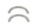 Chevrolet Silverado 3500 Classic Crankshaft Thrust Washer Set
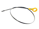 Chevrolet Silverado 3500 Classic Dipstick
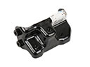 Chevrolet Silverado 3500 Classic Engine Mount Bracket
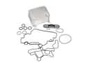 Chevrolet Silverado 3500 Classic Engine Oil Cooler
 Chevrolet Silverado 3500 Classic Exhaust Valve
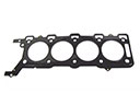 Chevrolet Silverado 3500 Classic Head Gasket
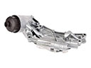 Chevrolet Silverado 3500 Classic Oil Cooler
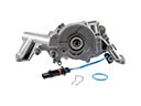 Chevrolet Silverado 3500 Classic Oil Pump
 Chevrolet Silverado 3500 Classic Pushrod
 Chevrolet Silverado 3500 Classic Timing Cover Gasket
 Chevrolet Silverado 3500 Classic Variable Timing Sprocket