ChevyParts
My Garage
My Account
Cart
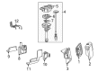
OEM GMC Savana 2500 Distributor
Ignition Distributor- Select Vehicle by Model
- Select Vehicle by VIN
Select Vehicle by Model
orMake
Model
Year
Select Vehicle by VIN
For the most accurate results, select vehicle by your VIN (Vehicle Identification Number).
2 Distributors found

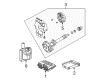
GMC Savana 2500 Distributor Assembly Part Number: 94672691
$383.36 MSRP: $775.86You Save: $392.50 (51%)Ships in 1-2 Business Days


GMC Savana 2500 Distributor Assembly Part Number: 12598210
GMC Savana 2500 Distributor
Want to cut long-term maintenance and repair costs? Choose OEM Distributor. Those parts deliver top durability you can trust. On our site, you'll find a huge catalog of genuine GMC Savana 2500 parts. Prices are unbeatable, so you can keep more in your pocket. Every OEM GMC Savana 2500 Distributor includes a manufacturer's warranty. You can also get an easy return policy that keeps buying risk free. Fast delivery, get your car on the road quickly. It's simple to search, compare, and order. Stop guessing about quality or fit. Order today and save with parts that last.
GMC Savana 2500 Distributor Parts and Q&A
- Q: How to replace the distributor on GMC Savana 2500?A:Begin Distributor replacement by shutting off the ignition followed by engine cover removal and sequentially disconnecting the air cleaner assembly and the air intake resonator assembly. Twist the wire boot of each spark plug wire 1/2 turn before you pull only the boot to disconnect them from the Distributor Cap. Use a screwdriver to take out the 2 screws holding the Distributor Cap in place against its housing then extract the electrical connector from the Distributor base. Toss these pieces away. Apply a grease pencil to mark two reference points on the Distributor housing and intake manifold then mark down the rotor position against the Distributor housing before removing the Distributor Cap. At Distributor removal you should observe the rotor moving counter-clockwise by about 42 degrees and should apply another alignment mark to the Distributor base while reassembly approaches. Unscrew the mounting clamp hold-down bolt before removing the Distributor. The new Distributor assembly requires two matching Distributor housing marks at positions analogous to those on the original component. To install the Distributor guide it into position while aligning the rotor segment with the second mark followed by placing and securing the Distributor base hole above the intake manifold mounting slot. Monitor the rotor's clockwise movement to reach 42 degrees while installing the Distributor. After placing the Distributor in position check that the rotor segment points towards the Distributor base mark. When the Distributor position does not align properly with the mark use the Distributor installation procedure again. Register Distributor mounting clamp bolt to 25 nm (18 lb ft) before installing the Distributor Cap and securing it with new screws tightened to 2.4 n.m (21 lb in). Reconnect the electrical connector then position the Spark Plug Wires and ignition coil wire with proper orientation before installation. The detector lamp warns you that you installed the Distributor incorrectly when p1345 dtc gets triggered. Installation procedure 2 requires top dead center (TDC) positioning of the number 1 cylinder compression stroke while matching the crankshaft balancer marks to front cover tabs. Guide the white paint mark from the Distributor's bottom stem through the pre-drilled indent situated in the gear. The Distributor must receive proper markings because improper reassembly methods could either block engine startup or lead to motor damage. The installation requires correctly positioned gears which lead you to guide the Distributor through the engine opening maintaining the flat housing section facing forward. When the rotor segment reaches complete insertion its position must match the Distributor base pointer. If not, repeat the procedure. Tighten the Distributor mounting clamp bolt to 25 n.m (18 lb ft) and then install the Distributor Cap while securing new screws at 2.4 n.m (21 lb in) torque. After reconnecting the electrical connector, place the Spark Plug Wires and ignition coil wire properly. An illuminated malfunction indicator lamp, together with the detection of dtc p1345, requires you to perform installation procedure 2 again. Finally, install the engine cover.
- Q: How to service and repair the distributor on GMC Savana 2500?A:The distributor repair process needs the removal of the engine cover as its first step. Normal wear shows as cap discoloration combined with white deposits nearby the terminals together with rotor cap yellowing coupled with darkening from carbon accumulation under the rotor segment. Driveability issues will determine the need for replacement. Look for cracks and small holes along with carbon tracks between the terminal traces on the cap. Use the DMM lead connected to the cap terminal to inspect all other terminals and the center carbon ball until testing all secondary terminals. Move the DMM base lead between each terminal while performing these tests. Check and replace the ignition cap when you find resistance readings other than infinity. Terminal inspections should take place for excessive corrosion leading to terminal cleaning before cap replacement if corrosion reaches high levels but normal buildup is expected. The rotor segment requires replacement if significant looseness is detected. Examine the housing for signs of cracks while testing shaft-to-bushing looseness with the shaft inserted into its place before installing a new housing assembly if the shaft shows noticeable movement. Finally, reinstall the engine cover.


Related GMC Savana 2500 Parts
 GMC Savana 2500 Automatic Transmission Shift Position Sensor Switch
 GMC Savana 2500 Back Up Light Switch
 GMC Savana 2500 Camshaft Position Sensor
 GMC Savana 2500 Coolant Temperature Sensor
 GMC Savana 2500 Distributor Cap
 GMC Savana 2500 Distributor Reluctor
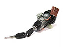 GMC Savana 2500 Igniter
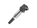 GMC Savana 2500 Ignition Coil
 GMC Savana 2500 Intake Manifold Temperature Sensor
 GMC Savana 2500 Spark Plug
 GMC Savana 2500 Throttle Position Sensor
 GMC Savana 2500 Vehicle Speed Sensor