
Popular OEM GMC C2500 Parts
- Body & Hardware Parts View More >
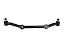
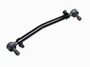
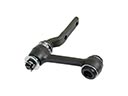
- Steering Parts View More >
- Electrical Parts View More >
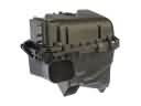
- Air & Fuel Delivery Parts View More >
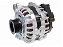
- Charging & Starting Parts View More >
- Engine Parts View More >
- Belts & Cooling Parts View More >
- Suspension Parts View More >
- Driveline & Axles Parts View More >
- Emission Control & Exhaust Parts View More >
- Transmission Parts View More >
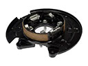
- Brakes Parts View More >

Why Buy Genuine GMC C2500 Parts From ChevyPartsGiant.com
Looking for real GMC C2500 parts? ChevyPartsGiant.com may be a better choice to find genuine parts at wallet-friendly prices. We sell only OEM GMC C2500 parts, ensuring perfect fit, reliability, and long-term performance. With our website, you can easily get access to the same parts found at local GMC stores. All components are produced by GMC and are exclusively fitted on GMC C2500 automobiles. By shopping at our store, you can enjoy the quality of the GMC factory without the high prices of brick-and-mortar facilities. We achieve this because we are an online store operating at lower costs, which we pass on to you. We also have a user-friendly platform where you can find and order genuine GMC C2500 parts swiftly. We are here to make your process of restoring a GMC C2500 or dealing with simple repairs quick and inexpensive. We also make it easy to obtain GMC C2500 parts at competitive shipping prices and a team of knowledgeable staff ready to take your order. Choose ChevyPartsGiant.com to save time and money, as well as keep your GMC C2500 in the good condition.
During 1960 GMC launched the C2500 as part of its C/K truck series and four-wheel-drive became accessible in later years starting in 1987. The GMC C2500 provided various engine choices which included a 250-cubic inch inline-six and multiple V8 engines with the 5.7L V8 among them alongside a 6.5L turbo-diesel engine for enhanced performance and towing capacity. The C2500 has a powerful transmission system that controls driving dynamics through its two-wheel or four-wheel drive capability for handling different road conditions. The GMT400 platform introduced in 1988 brought a new phase of GMC C2500 design that included advanced suspension technology and anti-lock braking system and a front-wheel independent suspension for superior handling capabilities. Between 1988 to 1998 the GMC C2500 strengthened its reputation through the addition of V8 engine capabilities and turbodiesel engine choices. Hydroformed chassis technology became part of the redesigned 1999 model which resulted in better structural integrity. The GMC C2500 completed its production cycle by 2001 because GMC introduced its present lineup of heavy trucks that used the HD model to replace it after 2004. Reliability along with maintenance performance stays intact when using OEM GMC C2500 components which are specifically designed according to the original construction and quality requirements of the manufacturer's specifications.
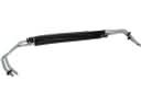
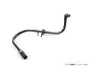
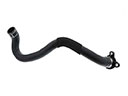
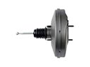
GMC C2500 groups concerns into hydraulic brake assist and steering, front linkage alignment, and cabin cooling. On the GMC C2500, a hard pedal with assist noise often traces to hydroboost or hose seepage. Check wet lines around the power steering assembly. Verify pump output and return restriction. Replace leaking hoses or the booster. Flush with the specified fluid and bleed air. For directional stability, the C2500 can wander and scrub toes after bumps. Wear at the steering idler arm and pitman interface increases free play. Measure joint lash, replace worn links, and align the front end to spec. Confirm straight tracking on the C2500 during a road weave test. For climate control, the C2500 may show weak cooling and oily residue on the condenser face. Check clutch engagement and pressure readings. A failing A/C compressor or condenser leak requires component replacement, evacuation, and an accurate recharge. Add dye and replace seals as needed. After repairs, road test the GMC C2500 on city streets and highway. Validate assist feel, steering return, and outlet temperature stability. Record pressures, alignment angles, and reservoir level so GMC service history remains clear. These steps help the C2500 stay predictable and quiet under load.
GMC C2500 Parts and Q&A
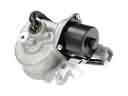
- Q: How to service and repair the starter motor on GMC C2500?A:In order to service and repair the starter motor, one has to disconnect the negative battery cable and lift the vehicle. Take off protective shields and the starter, take off the engine oil level sensor and, 4WD, tune the front axle mounting bracket. Take out and re-fit the starter reconnecting cables and tightening bolts where required.
- Q: How to service the Air Filter element on GMC C2500?A:The air filter service requires loosening the clamp on the air duct and unplugging the MAF/IAT sensor. Open the air filter by removing the top cover of the air cleaner. Check and check or change it accordingly. Install the filter again, put on the cover and reconnect the electrical connector.
- Q: How to Service and Repair a Flywheel in Both Automatic and Manual Transmissions on GMC C2500?A:To service and repair the flex plate, first disconnect the negative battery cable. Remove the automatic transmission or manual transmission following the appropriate procedures, then take out the flywheel. Clean and inspect it thoroughly. Reinstall the flywheel and transmission, then reconnect the negative battery cable.


