ChevyParts
My Garage
My Account
Cart
OEM GMC C2500 Air Bag Clockspring
Steering Wheel Airbag Coil- Select Vehicle by Model
- Select Vehicle by VIN
Select Vehicle by Model
orMake
Model
Year
Select Vehicle by VIN
For the most accurate results, select vehicle by your VIN (Vehicle Identification Number).
2 Air Bag Clocksprings found

GMC C2500 Clockspring Part Number: 26087273
GMC C2500 Clockspring Part Number: 19330851
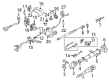
GMC C2500 Air Bag Clockspring
Want to cut long-term maintenance and repair costs? Choose OEM Air Bag Clockspring. Those parts deliver top durability you can trust. On our site, you'll find a huge catalog of genuine GMC C2500 parts. Prices are unbeatable, so you can keep more in your pocket. Every OEM GMC C2500 Air Bag Clockspring includes a manufacturer's warranty. You can also get an easy return policy that keeps buying risk free. Fast delivery, get your car on the road quickly. It's simple to search, compare, and order. Stop guessing about quality or fit. Order today and save with parts that last.
The GMC C2500 Air Bag Clockspring is a recommended assembly mainly used for GMC C2500 automobiles that help in operating the airbag system by offering electrical connectivity between a vital part that is the airbag module and the electrical systems of the automobile. This functionality is central in the right deployment of the air bagging system in cases of an accident, boosting greatly the safety of drivers and the passengers. As it is expected to be a part of GMC C2500 series, this vehicle comes with a clock spring that can support its frequent usage and various GMC C2500 models that have been produced from the year 1960 to 1998. Thus, the C2500, which has an effectively constructed body and the ability to transport a large amount of cargo, appreciates the efficiency of the Air Bag Clockspring, which guarantees the availability of safety systems. Constructed using hard wearing materials including a hybrid of plastic and metal, the GMC C2500 Air Bag Clockspring is ideal in the automotive market since it lasts longer. Added to that, the fact that it can fit GMC C2500 with several trims such as Base, Deluxe, Custom, Sierra, and Sierra Grande makes it important. In this way, the Air Bag Clockspring is instrumental in increasing the overall safety and productivity of GMC C2500 and consistently supporting GMC's brand image as a heavy-duty vehicle for any resolving job which will allow the driver to count on his car for many years.
GMC C2500 Air Bag Clockspring Parts Questions & Experts Answers
- Q: How to Service and Repair the Air Bag Clockspring Assembly on GMC C2500?A:First service air bag clock spring assembly demands disabling the sir system followed by Steering Wheel removal along with tilt lever (if present) and upper and lower steering column trim covers. Start by taking out the multi-function lever then push the wire harness assembly from its holder in the wire harness strap before removing all three wire harness straps along with the wire harness strap from the upper tilt head assembly. Next remove the clock spring retaining clip and clock spring because they both require removal of the wave washer. Secure all fasteners before torque application to stop component harm. After lining up the block tooth on the race and upper shaft assembly to face the 12 o'clock position of the air bag clock spring maintain precise centering before installing the wave washer. An un-centered state of the clock spring occurs when a separation occurs between the steering column and steering gear or when the centering spring presses down as technicians remove the clock spring. Set the pre-centered clock spring into position and dispose of the centering tab while using the horn tower to align with canceling cam assembly inner ring projections on the outer ring. Closely pull the lower clock spring wire while inspecting it for all kinks to guarantee clear paths for the shaft lock mechanism. Set the clock spring retaining ring inside the upper shaft assembly groove then position the wire harness assembly through the wire strap before mounting the wire harness strap to the upper tilt head assembly. Enable sir system only after you reassemble all components including 3 wire harness straps and multi-function switch lever and upper and lower steering column trim covers and tilt lever (if equipped) and Steering Wheel assembly.

Related GMC C2500 Parts
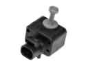 GMC C2500 Air Bag Sensor
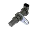 GMC C2500 Crankshaft Position Sensor
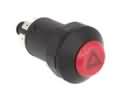 GMC C2500 Hazard Warning Switch
 GMC C2500 Headlight Relay
 GMC C2500 Headlight Switch
 GMC C2500 Horn
 GMC C2500 Ignition Control Module
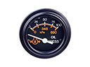 GMC C2500 Oil Pressure Gauge
 GMC C2500 Seat Switch Panel
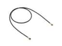 GMC C2500 Speedometer Cable
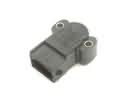 GMC C2500 Throttle Position Sensor
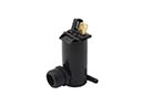 GMC C2500 Washer Pump