ChevyParts
My Garage
My Account
Cart
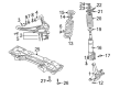
OEM 2001 Chevrolet Tracker Steering Knuckle
Front Steering Knuckle- Select Vehicle by Model
- Select Vehicle by VIN
Select Vehicle by Model
orMake
Model
Year
Select Vehicle by VIN
For the most accurate results, select vehicle by your VIN (Vehicle Identification Number).
2 Steering Knuckles found


2001 Chevrolet Tracker Knuckle Part Number: 91175803
Product Specifications- Other Name: Knuckle, Steering
- Item Weight: 11.30 Pounds
- Item Dimensions: 14.1 x 14.8 x 8.2 inches
- Condition: New
- Fitment Type: Direct Replacement
- SKU: 91175803
- Warranty: This genuine part is guaranteed by GM's factory warranty.
2001 Chevrolet Tracker Knuckle Part Number: 91175802
Product Specifications- Other Name: Knuckle, Steering
- Item Weight: 10.30 Pounds
- Item Dimensions: 13.7 x 12.6 x 4.6 inches
- Condition: New
- Fitment Type: Direct Replacement
- SKU: 91175802
- Warranty: This genuine part is guaranteed by GM's factory warranty.
2001 Chevrolet Tracker Steering Knuckle
With a comprehensive array of OEM 2001 Chevrolet Tracker Steering Knuckle, from fuel pumps to door handles, our website is a one-stop-shop for your needs. All our genuine 2001 Chevrolet Tracker Steering Knuckle are backed by the manufacturer's warranty and are offered at competitive prices in the market. Rest assured, you can shop with complete confidence.
2001 Chevrolet Tracker Steering Knuckle Parts Questions & Experts Answers
- Q: How to service and repair the steering knuckle on 2001 Chevrolet Tracker?A: Vehicle servicing and Steering Knuckle repairs require you to firstly elevate the vehicle then support it. Start by removing the tire-wheel combination and then the brake rotor before proceeding. Identify the hub along with bearings and seals to remove them next. First remove the Tie Rod nut before using the universal steering linkage puller (J 24319-B) to disconnect the Tie Rod from the knuckle. The procedure starts by loosening four bolts from the brake shield then removing the brake shield from its position on the Spindle. Separate the knuckle from the Spindle which holds the drive shaft bearing and also extract the Control Arm ball stud nut. The extreme coil spring pressure requires careful attention when removing the coil spring so professionals should support the lower Control Arm with a jack. Once the lower Control Arm receives support use the universal steering linkage puller (J 24319-B) to remove the knuckle from the ball stud . Proceed by taking out the two nuts and two bolts from the strut bracket. Extract both the front drive shaft's outer seal and inner seal from the knuckle. To install the drive shaft inner seal to the knuckle follow these steps: apply wheel bearing lubricant gm p/n 1051344 or equivalent to both the inner seal lip and hollow until they reach more than 60 percent of space availability. Repetition of the lubrication process follows before installing the outer seal. Afterward install the knuckle to the ball stud and use a jack to support the lower Control Arm. Tighten two nuts and two bolts on the strut bracket to 95 nm (69 ft.lb) torque. Secure the new lower Control Arm ball stud nut to 60 nm (43.5 ft. Lbs.) torque while removing the jack. After attaching the Tie Rod to the knuckle install a new Tie Rod nut which requires 43 nm (31.5 ft. Lbs.) of torque. The wheel Spindle mating surface requires coating with general motors sealer p/n 1052366 or an equivalent product. Similarly, the wheel Spindle's recess needs wheel bearing lubricant p/n 1051344 or its equivalent poured in at 10 g (0.4 oz.) amounts. Fasten the wheel Spindle to its knuckle position next install brake shield onto the Spindle by securing all four bolts at 50 nm (36.5 ft. Lbs.). After replacing the wheel hub along with bearings and seals and brake rotor and tire-wheel assembly place the vehicle back onto the ground for wheel alignment assessment and possible adjustment.
Related 2001 Chevrolet Tracker Parts
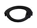 2001 Chevrolet Tracker Coil Spring Insulator
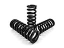 2001 Chevrolet Tracker Coil Springs
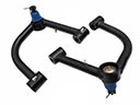 2001 Chevrolet Tracker Control Arm
 2001 Chevrolet Tracker Control Arm Bolt
 2001 Chevrolet Tracker Control Arm Bushing
 2001 Chevrolet Tracker Shock Absorber
 2001 Chevrolet Tracker Shock And Strut Mount
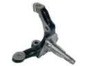 2001 Chevrolet Tracker Spindle
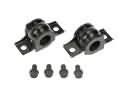 2001 Chevrolet Tracker Sway Bar Bracket
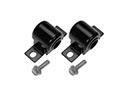 2001 Chevrolet Tracker Sway Bar Bushing
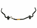 2001 Chevrolet Tracker Sway Bar Kit
 2001 Chevrolet Tracker Sway Bar Link