ChevyParts
My Garage
My Account
Cart
OEM 2004 Chevrolet Astro Intake Manifold
Engine Intake Manifold- Select Vehicle by Model
- Select Vehicle by VIN
Select Vehicle by Model
orMake
Model
Year
Select Vehicle by VIN
For the most accurate results, select vehicle by your VIN (Vehicle Identification Number).
2 Intake Manifolds found


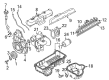
2004 Chevrolet Astro Intake Manifold Part Number: 17113542
Product Specifications- Other Name: Manifold Kit, Engine Fuel Intake Manifold; Manifold
- Position: Upper
- Replaces: 17113213
- Item Weight: 3.30 Pounds
- Item Dimensions: 7.4 x 13.5 x 12.5 inches
- Condition: New
- Fitment Type: Direct Replacement
- SKU: 17113542
- Warranty: This genuine part is guaranteed by GM's factory warranty.
2004 Chevrolet Astro Intake Manifold, Lower Part Number: 88894294
Product Specifications- Other Name: Manifold Kit, Lower Intake; Manifold; Manifold Kit, Engine Fuel Intake Manifold
- Position: Lower
- Item Weight: 19.50 Pounds
- Item Dimensions: 21.7 x 17.8 x 15.2 inches
- Condition: New
- Fitment Type: Direct Replacement
- SKU: 88894294
- Warranty: This genuine part is guaranteed by GM's factory warranty.
2004 Chevrolet Astro Intake Manifold
With a comprehensive array of OEM 2004 Chevrolet Astro Intake Manifold, from fuel pumps to door handles, our website is a one-stop-shop for your needs. All our genuine 2004 Chevrolet Astro Intake Manifold are backed by the manufacturer's warranty and are offered at competitive prices in the market. Rest assured, you can shop with complete confidence.
2004 Chevrolet Astro Intake Manifold Parts and Q&A
- Q: How to replace the upper intake manifold on 2004 Chevrolet Astro?A: Removal of the engine cover and air cleaner duct are required to remove the upper intake manifold. Disassemble a number of cables and hose, and take out the upper intake manifold and gasket. Wipe down and check the damage. Next is to install new manifold, reconnectivity, and finally to replace engine cover.
Related 2004 Chevrolet Astro Parts
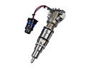 2004 Chevrolet Astro Fuel Injector
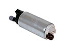 2004 Chevrolet Astro Fuel Pump
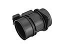 2004 Chevrolet Astro Mass Air Flow Sensor
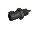 2004 Chevrolet Astro Air Charge Temperature Sensor
 2004 Chevrolet Astro Air Filter
 2004 Chevrolet Astro Air Hose
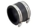 2004 Chevrolet Astro Air Intake Coupling
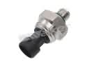 2004 Chevrolet Astro Fuel Pressure Sensor
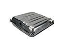 2004 Chevrolet Astro Fuel Tank
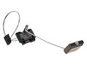 2004 Chevrolet Astro Fuel Tank Sending Unit
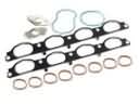 2004 Chevrolet Astro Intake Manifold Gasket
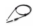 2004 Chevrolet Astro Throttle Cable