ChevyParts
My Garage
My Account
Cart
OEM 2009 Chevrolet Trailblazer CV Boot
Axle Boot- Select Vehicle by Model
- Select Vehicle by VIN
Select Vehicle by Model
orMake
Model
Year
Select Vehicle by VIN
For the most accurate results, select vehicle by your VIN (Vehicle Identification Number).
2 CV Boots found


2009 Chevrolet Trailblazer Boot Kit, Front Part Number: 26059671
$36.90 MSRP: $57.80You Save: $20.90 (37%)Product Specifications- Other Name: Boot Kit, Front Axle; CV Boot; Outer Boot
- Position: Front
- Item Weight: 1.70 Pounds
- Item Dimensions: 8.0 x 7.0 x 6.8 inches
- Condition: New
- Fitment Type: Direct Replacement
- Require Quantity: 2
- SKU: 26059671
- Warranty: This genuine part is guaranteed by GM's factory warranty.


2009 Chevrolet Trailblazer Boot Kit, Front Part Number: 26059675
Product Specifications- Other Name: Boot Kit, Front Wheel Drive Axle Shaft; CV Boot; Inner Boot; Boot Kit, Front Axle
- Position: Front
- Item Weight: 1.60 Pounds
- Item Dimensions: 6.8 x 6.2 x 6.2 inches
- Condition: New
- Fitment Type: Direct Replacement
- Require Quantity: 2
- SKU: 26059675
- Warranty: This genuine part is guaranteed by GM's factory warranty.
2009 Chevrolet Trailblazer CV Boot
With a comprehensive array of OEM 2009 Chevrolet Trailblazer CV Boot, from fuel pumps to door handles, our website is a one-stop-shop for your needs. All our genuine 2009 Chevrolet Trailblazer CV Boot are backed by the manufacturer's warranty and are offered at competitive prices in the market. Rest assured, you can shop with complete confidence.
2009 Chevrolet Trailblazer CV Boot Parts and Q&A
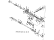
- Q: How to replace the outer CV Boot and CV Joint on 2009 Chevrolet Trailblazer?A: To replace the wheel drive shaft outer joint and boot. First, fix the halfshaft into a vise with protective covers to cover its jaws. Use a hand grinder to precisely saw through the two swage rings without causing harm to the outer race. Push the seal of the halfshaft away from the outer race of the constant velocity (CV) joint and remove all the grease from the cv joint face. Deploy j 8059 in order to move halfshaft retaining snap ring's ears apart on the inner race. Extract the cv joint from the halfshaft and throw away old seal. Using a brass drift, knock and roll the cage tilting all balls out of the cage. Rotate the cage and inner race at a 90-degree angle to match the out race lands, then pull the cage and inner race out. Pry the inner race off the cage by turning it upward and degrease every part of the cv joint and examine it for any unusual wear or damage. Clean the halfshaft bar using wire brush for rust in the seal mounting area. Examine all parts for damage and put on a light coat of suggested grease on the inner and outer race grooves. Put the inner race in the cage with a rotation downward, in line with the cage windows and then put the cage and inner race into the outer race. With the help of a brass drift, tip the cage and place the first ball, carry on doing this until ball installations are complete. Pack the cv joint seal and assembly with the pre measured grease from the kit and then fit the new small swage clamp onto the cv joint seal and the large retaining clamp on the seal. Complete sealing to the joint seal groove on the halfshaft bar using a small end of the cv joint seal and align the outboard end of the halfshaft assembly on j 41048 to make sure the sealing of swage clamp is induced. Temporarily insert and hand-tighten the bolts and align the seal, halfshaft bar, and swage clamp, tightening each bolt in 180 degrees increments using a ratchet wrench. Weaken the brittleness of the bolts and disengage the dies, and inspect for swage clamps deformities and the reinsertion, if necessary. Position the retaining ring side of cv joint inner race towards the halfshaft bar while placing the retaining snap ring at the cv joint inner race, which is insert into halfshaft bar groove when correctly positioned. Slide the cv joint on to the halfshaft bar ensuring that the there is engagement, pull on it. Slide the large diameter of the cv joint seal onto the cv joint outer race and place its lip into the groove, squeeze to get out any air. Finally, apply the large retaining clamp to the housing with j 35910, a breaker bar and a torque wrench with the torque wrench tightened 176 nm (130 lb ft) to the dimension of the gap visited through the clamp ear.
Related 2009 Chevrolet Trailblazer Parts
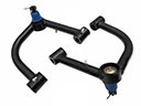 2009 Chevrolet Trailblazer Control Arm
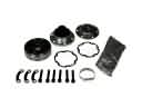 2009 Chevrolet Trailblazer CV Joint
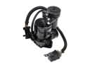 2009 Chevrolet Trailblazer Air Suspension Compressor
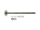 2009 Chevrolet Trailblazer Axle Shaft
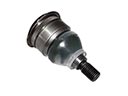 2009 Chevrolet Trailblazer Ball Joint
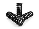 2009 Chevrolet Trailblazer Coil Springs
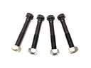 2009 Chevrolet Trailblazer Control Arm Bolt
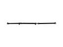 2009 Chevrolet Trailblazer Drive Shaft
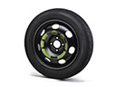 2009 Chevrolet Trailblazer Spare Wheel
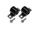 2009 Chevrolet Trailblazer Sway Bar Bushing
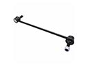 2009 Chevrolet Trailblazer Sway Bar Link
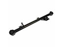 2009 Chevrolet Trailblazer Trailing Arm