ChevyParts
My Garage
My Account
Cart
OEM Chevrolet Corvette Clutch Disc
Friction Disc- Select Vehicle by Model
- Select Vehicle by VIN
Select Vehicle by Model
orMake
Model
Year
Select Vehicle by VIN
For the most accurate results, select vehicle by your VIN (Vehicle Identification Number).
7 Clutch Discs found

Chevrolet Corvette Disc Part Number: 24230988
$224.17 MSRP: $352.73You Save: $128.56 (37%)Ships in 1-3 Business DaysChevrolet Corvette Pressure Plate Part Number: 24278525
$866.14 MSRP: $1368.65You Save: $502.51 (37%)Ships in 1-3 Business Days

Chevrolet Corvette Pressure Plate Part Number: 24260226
Chevrolet Corvette Pressure Plate Part Number: 12570280
Chevrolet Corvette Disc Part Number: 14084177

Chevrolet Corvette Disc Part Number: 12570808

Chevrolet Corvette Disc Part Number: 10174491
Chevrolet Corvette Clutch Disc
Want to cut long-term maintenance and repair costs? Choose OEM Clutch Disc. Those parts deliver top durability you can trust. On our site, you'll find a huge catalog of genuine Chevrolet Corvette parts. Prices are unbeatable, so you can keep more in your pocket. Every OEM Chevrolet Corvette Clutch Disc includes a manufacturer's warranty. You can also get an easy return policy that keeps buying risk free. Fast delivery, get your car on the road quickly. It's simple to search, compare, and order. Stop guessing about quality or fit. Order today and save with parts that last.
Chevrolet Corvette Clutch Disc Parts Questions & Experts Answers
- Q: How to service and repair the clutch disc on Chevrolet Corvette?A:Start the Clutch Disc repair and service by disconnecting the negative Battery Cable then supporting the vehicle in an elevated position. You should begin by removing the Catalytic Converter and driveline support assembly with transaxle then evaluate the engine Flywheel inspection cover bolts and remove the cover itself. Start by rotating the engine Flywheel and releasing the visible clutch Pressure Plate bolts through multiple rotations for every bolt. First remove all remaining clutch Pressure Plate bolts before taking out the clutch Pressure Plate and clutch driven plate. Examine the clutch Pressure Plate alongside the clutch driven plate to check for damage and wear. Also check whether the engine Flywheel shows any indications of damage. Before the clutch driven plate and clutch Pressure Plate get installed onto the engine Flywheel, make any necessary adjustments to the clutch Pressure Plate. Putting first touch tension on visible clutch Pressure Plate bolts and turning the engine Flywheel in the specified direction resulted in each bolt's initial finger-tight state. This process was repeated to achieve finger-tight installation on all bolts. The pilot bushing installer/clutch alignment arbor (J 38836) enables alignment of the clutch driven plate against the Pilot Bearing. Follow this sequence when tightening clutch Pressure Plate bolts at three stages then apply 70 nm (52 foot pounds) during the fourth stage. Reattach the engine Flywheel inspection cover and bolting hardware with a torque setting of 25 nm (18 ft. Lbs.). Put back all components starting from driveline support assembly through transaxle before installing the Catalytic Converter. Conclusion of work includes reconnecting the negative Battery Cable with proper bolt torque at 15 nm (11 ft. Lbs.) and programming transmitters before lowering the vehicle down.
Related Chevrolet Corvette Parts
 Chevrolet Corvette Automatic Transmission Seal
 Chevrolet Corvette Automatic Transmission Shifter
 Chevrolet Corvette Clutch Fork
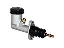 Chevrolet Corvette Clutch Master Cylinder
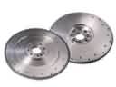 Chevrolet Corvette Flywheel
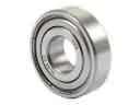 Chevrolet Corvette Pilot Bearing
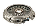 Chevrolet Corvette Pressure Plate
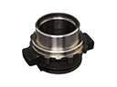 Chevrolet Corvette Release Bearing
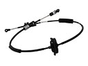 Chevrolet Corvette Shift Cable
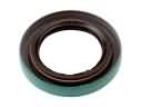 Chevrolet Corvette Transfer Case Seal
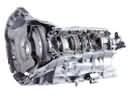 Chevrolet Corvette Transmission Assembly
 Chevrolet Corvette Transmission Gasket