ChevyParts
My Garage
My Account
Cart
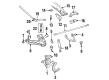
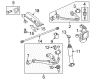
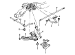
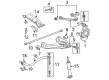
OEM Chevrolet Suburban 1500 Torsion Bar
Suspension Torsion Bar- Select Vehicle by Model
- Select Vehicle by VIN
Select Vehicle by Model
orMake
Model
Year
Select Vehicle by VIN
For the most accurate results, select vehicle by your VIN (Vehicle Identification Number).
12 Torsion Bars found


Chevrolet Suburban 1500 Torsion Bar, Front Driver Side Part Number: 19330060
$312.71 MSRP: $492.03You Save: $179.32 (37%)
Chevrolet Suburban 1500 Torsion Bar, Front Passenger Side Part Number: 19330059
$312.71 MSRP: $492.03You Save: $179.32 (37%)Ships in 1-3 Business Days


Chevrolet Suburban 1500 Torsion Bar, Front Driver Side Part Number: 19330058
$312.77 MSRP: $492.12You Save: $179.35 (37%)

Chevrolet Suburban 1500 Torsion Bar, Front Passenger Side Part Number: 19330057
$312.77 MSRP: $492.12You Save: $179.35 (37%)

Chevrolet Suburban 1500 Torsion Bar, Front Part Number: 15048312
$257.64 MSRP: $405.40You Save: $147.76 (37%)Ships in 1-3 Business Days


Chevrolet Suburban 1500 Torsion Bar, Front Passenger Side Part Number: 19332946
$257.82 MSRP: $405.67You Save: $147.85 (37%)
Chevrolet Suburban 1500 Torsion Bar, Front Driver Side Part Number: 19332945
$257.82 MSRP: $405.67You Save: $147.85 (37%)Chevrolet Suburban 1500 Torsion Bar, Front Part Number: 19332931

Chevrolet Suburban 1500 Torsion Bar
Want to cut long-term maintenance and repair costs? Choose OEM Torsion Bar. Those parts deliver top durability you can trust. On our site, you'll find a huge catalog of genuine Chevrolet Suburban 1500 parts. Prices are unbeatable, so you can keep more in your pocket. Every OEM Chevrolet Suburban 1500 Torsion Bar includes a manufacturer's warranty. You can also get an easy return policy that keeps buying risk free. Fast delivery, get your car on the road quickly. It's simple to search, compare, and order. Stop guessing about quality or fit. Order today and save with parts that last.
Chevrolet Suburban 1500 Torsion Bar Parts and Q&A
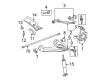
- Q: How to replace the torsion bar on Chevrolet Suburban 1500?A:To change the Torsion Bar, one must lift and support the vehicle. Mount the Torsion Bar unloading/loadingtool(J 36202) to the adjustment arm and crossmember and tighten the tension on the arm till pressure is taken off the adjustment bolt and the adjuster bolt. Mark the adjustment bolt and note the number of turns necessitated for removal. Then, one needs to disconnect the adjustment bolt and the adjuster nut then adjustment bolt and adjuster nut for k25/35 series of mw3, c5f, and cop (MT1). Pull the j 36202 out so that the Torsion Bar is unloaded and move the Torsion Bar forward to clear the adjustment arm holding it with your hand. Unbolt the Torsion Bar crossmember bolts from the weld nuts from the upper link mounting nuts and bolts for the k25/35 series with mt1, mw3, c5f, and cop. Make a note of where the torsion bars are situated because the left and right bars are different and then pull the torsion bars from the vehicle. For installation, the torsion bars are mounted on the lower Control Arm, and the Torsion Bar crossmember installed. Install the Torsion Bar crossmember bolts to the weld nuts and bring them to the required torques of 95 nm (70 ft. Lbs). Then mount the upper link mounting nuts and bolts for the k 25/35 series with mt1, mw3 c5f, and cop, tightening the nut to 95 nm 70 ft. Lbs. While supporting the adjustment arm, slide the Torsion Bar to the rear until it engages the adjustment arm completely and then re-install the j 36202 to the adjustment arm as well as to the crossmember. Tighten the adjustment arm to load the Torsion Bar, making sure the adjustment bolt goes in with the same number of turns taken in removal. Lastly, thread the adjustment bolt and the adjuster nut , then the adjustment bolt and the adjuster nut with the k 25/35 series with mt1, mw3, c5f & cop. Remove the j 36202 and let the adjustment bolt take up the tension of the Torsion Bar and then remove the safety stands lowering the vehicle and measure the z height, adjust the adjustment bolt as necessary to obtain the desired height.

Related Chevrolet Suburban 1500 Parts
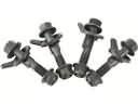 Chevrolet Suburban 1500 Alignment Bolt
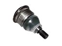 Chevrolet Suburban 1500 Ball Joint
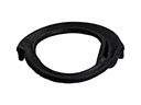 Chevrolet Suburban 1500 Coil Spring Insulator
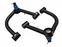 Chevrolet Suburban 1500 Control Arm
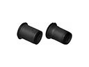 Chevrolet Suburban 1500 Control Arm Bushing
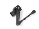 Chevrolet Suburban 1500 Ride Height Sensor
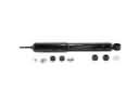 Chevrolet Suburban 1500 Shock Absorber
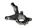 Chevrolet Suburban 1500 Steering Knuckle
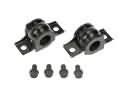 Chevrolet Suburban 1500 Sway Bar Bracket
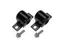 Chevrolet Suburban 1500 Sway Bar Bushing
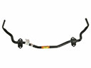 Chevrolet Suburban 1500 Sway Bar Kit
 Chevrolet Suburban 1500 Sway Bar Link