
Popular OEM Chevrolet Suburban 1500 Parts
- Body & Hardware Parts View More >
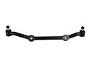
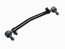
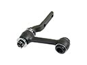
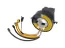
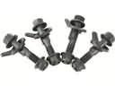
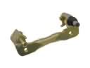
- Steering Parts View More >
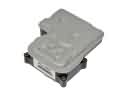
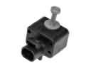
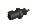
- Electrical Parts View More >
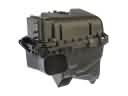
- Air & Fuel Delivery Parts View More >
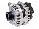
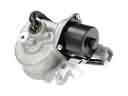
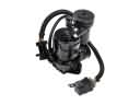
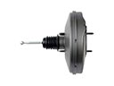
- Charging & Starting Parts View More >
- Engine Parts View More >
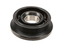
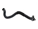
- Belts & Cooling Parts View More >
- Suspension Parts View More >
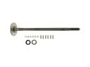
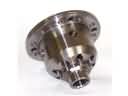
- Driveline & Axles Parts View More >
- Emission Control & Exhaust Parts View More >
- Transmission Parts View More >
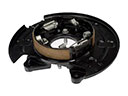
- Brakes Parts View More >

Why Buy Genuine Chevrolet Suburban 1500 Parts From ChevyPartsGiant.com
Looking for real Chevrolet Suburban 1500 parts? ChevyPartsGiant.com may be a better choice to find genuine parts at wallet-friendly prices. We sell only OEM Chevrolet Suburban 1500 parts, ensuring perfect fit, reliability, and long-term performance. With our website, you can easily get access to the same parts found at local Chevrolet stores. All components are produced by Chevrolet and are exclusively fitted on Chevrolet Suburban 1500 automobiles. By shopping at our store, you can enjoy the quality of the Chevrolet factory without the high prices of brick-and-mortar facilities. We achieve this because we are an online store operating at lower costs, which we pass on to you. We also have a user-friendly platform where you can find and order genuine Chevrolet Suburban 1500 parts swiftly. We are here to make your process of restoring a Chevrolet Suburban 1500 or dealing with simple repairs quick and inexpensive. We also make it easy to obtain Chevrolet Suburban 1500 parts at competitive shipping prices and a team of knowledgeable staff ready to take your order. Choose ChevyPartsGiant.com to save time and money, as well as keep your Chevrolet Suburban 1500 in the good condition.
The Chevrolet Suburban 1500 made its market entry through December 1991 as the 1992 model based on GMT400 platform technologies derived from C/K pickup models. The 5.7L V8 Vortec powertrain produces 255 hp and 330 lb-ft of torque according to its specifications though an optional request for a 6.5L turbodiesel engine results in 380 lb-ft of torque. The Chevrolet Suburban 1500 comes with a transmission system known as the 4L60 which delivers both reliable performance and operation as its automatic four-speed component. The Suburban 1500 features a solid rear axle with improved suspension, enhancing driving performance and better managing road impacts compared to previous leaf spring setups. Its off-road readiness increases because ground clearance stands at 6.9 inches and the ramp angle reaches 18 degrees. The estimated fuel economy for the diesel-powered Chevrolet Suburban 1500 is around 15-17 mpg which matches the performance expectations of similar-sized vehicles with comparable features. Drivers can select between rear-wheel drive and four-wheel drive options when purchasing a Chevrolet Suburban 1500. Using factory-original Chevrolet Suburban 1500 parts remains essential for keeping the vehicle performance and integrity because these parts undergo manufacturer-defined testing to guarantee proper vehicular operation. The Chevrolet Suburban 1500 maintains high demand through successive years because of its dedication to quality which led to its sustained sales numbers reaching 113,000 units since 1998.
Owners of the Chevrolet Suburban 1500 have reported various faults in the fuel, emissions, and drivetrain divisions. The Suburban 1500 can exhibit some erratic fuel system gauge that drops or sticks. The reason is that a level sensor somewhere deep in the tank is worn and shows an incorrect position. The fuel pump module replacement ensures that even high-mileage vehicles can show accurate readings and a reliable start-up. The evaporative emissions category of the Suburban 1500 may cause a check engine light when being fueled. A loose or cracked gas cap will allow vapor leaks to set EVAP codes. Reinstall the new cap and clear codes, and then check to make sure it is properly sealed during a drive cycle. In the 4WD timeline, 1500 Suburban 1500 displays a service 4WD message, loss of axle engagement on the front axle. The transfer case position sensor/selector switch may get faulty and may override the module. Exchange the transfer case position sensor, then check the integrity of the wires and reset the control module. Chevrolet drivers are also advised to check the ground and connections where they are corroded. The Suburban 1500 should be scanned after repairs have been done, and even take it on a road test. Chevrolet service information suggests checking for coughs on stored codes and freeze frames. These steps maintain a Chevrolet Suburban 1500 smoothly, coolly, and it is ready to work with no additional parts.
Chevrolet Suburban 1500 Parts Questions & Answers
- Q: How to replace the underhood fuse box on Chevrolet Suburban 1500?A:The first step when replacing an underhood electrical center or junction block requires disconnecting the negative Battery Cable and taking out the left fender upper brace. You must raise the electrical center brace cover from its base to expose the tabs and after that remove all fuses and relays. A grip of the tab will unlock the electrical center from its stud location at while you remove each connector through its bolt . All electrical connectors must be removed from the block while using tabs to raise the electrical center upward from the housing. The replacement of the engine electrical center bracket requires removing the 4 retaining bolts which allows extraction of the assembly from its fender position. The engine electrical center bracket assembly needs to be secured to the front fender by using 4 retaining bolts which must be tightened to 9 n.m (80 lb in). Secure the electrical center block stubs into their designated slots before the tabs catch them securely. Subsequently, connect wire connectors to the electrical center block bottom half and fasten them using bolts which need tightening to 9 n.m (80 lb in). The electrical center block must be placed correctly so that its tabs secure the block in position. The installation order requires officials to first place the lower cover section before locating fuses and relays according to the information chart to finish with the cover application. The fender upper brace installation requires you to attach it using 4 bolts which must be tightened to 25 n.m (18 lb ft). After reconnecting the negative cable verify every component works correctly by starting the vehicle.
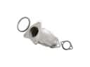
- Q: How to replace the catalytic converter on Chevrolet Suburban 1500?A:After supporting the vehicle and transmission with proper equipment, begin the Catalytic Converter replacement process. Start by removing the transmission mount nuts to transmission support then lift the transmission away from the support before you extract the transmission support crossmember bolts and nuts leading to the crossmember's removal. The engine harness along with its oxygen sensor pigtail requires clip removal. After that disconnect the connector position assurance (CPA) retainers and oxygen sensor electrical connectors. Unclip oxygen sensor connectors both from the hose clip and transmission crossmember followed by a second disconnect of the oxygen sensor cpa retainers and electrical connectors (1, 2). Follow this sequence to remove the Catalytic Converter - first unfasten the left and right exhaust manifold pipe nuts and next disconnect the exhaust muffler nuts then remove the Catalytic Converter. You should apply gm p/n 12377953 anti-seize compound with equivalent material to old oxygen sensor threads before installation. Torque the sensors to 42 nm (31 ft. Lbs.). Drive the right and left exhaust manifold pipe nuts halfway by hand before torqueing them to 50 nm (39 ft. Lbs.). Next, install the new Catalytic Converter alongside new exhaust manifold pipe seals mounted on the exhaust manifolds. Use 40 nm (30 ft. Lbs.) torque when tightening all exhaust muffler nuts. The oxygen sensor electrical connectors (1, 2) and cpa retainers need installation before you secure the oxygen sensor electrical connectors to the hose clip and transmission crossmember. First tighten the transmission support crossmember bolts and nuts to 95 nm (70 ft. Lbs.) then reinstall the crossmember before installing the engine harness and oxygen sensor pigtail in their clips. Finally reattach the cpa retainers and oxygen sensor electrical connectors. Place the transmission mount on the support then bolt it to the transmission support nuts while torquing them to 40 nm (30 ft. Lbs.). Lower the vehicle while removing the transmission jack.
- Q: How to replace the emblem/nameplate on the end gate on Chevrolet Suburban 1500?A:Obtaining tools to replace the emblem/nameplate at the end gate (excluding RPO B4U) begins with building the following list of tools: Use Heat Gun J 25070 together with 3M(TM) P/N 07501 Molding Adhesive Remover Disk from 3M(TM) Scotch Brite. Heat Gun (J 25070) and 3M(TM) Scotch Brite Molding Adhesive Remover Disk (3M(TM) P/N 07501). Use protective tape first then position it around the emblem area before beginning. Use a Heat Gun (J 25070) to heat the emblem/nameplate from 152 mm away (6.0 inches) for about 30 seconds in circular motions. Use a plastic flat tool for careful endgate surface emblem/nameplate removal. Clean both the endgate panel surface and the emblem/nameplate rear surface completely free of adhesive by using a 3M(TM) P/N 07501 Molding Adhesive Remover Disk in combination with varnish makers and painters (VMP) naptha. When no marks indicate the emblem/nameplate position, install tape. Use the Heat Gun (J 25070) to warm the endgate surface to 21°C (70°F) and above while maintaining contact between both the emblem/nameplate and adhesive backing. Press the front side of the emblem/nameplate onto the endgate panel as you gradually remove its backing. Use hand pressure to press-roll the emblem/nameplate until it sticks properly then check bonding before removing the tape from the endgate emblem area.
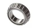
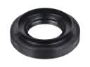
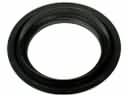
- Q: What tools are required to replace the front inner axle wheel seal or bearing on Chevrolet Suburban 1500?A:The replacement of front drive axle inner axle seal or bearing requires the following tools: housing drive gear seal installer (J22833) for 9.25 inch axle along with j2619-01 slide hammer along with bushing and bearing remover tools j29369-1, j29369-2 for 2-3 inch use, output shaft seal installer (J36600) for 8.25 inch axle and axle tube bearing installer (J36609). A technician should first lift the vehicle before draining the differential carrier assembly. To work on right side seal or bearing you must first separate the differential carrier case from its inner Axle Shaft housing assembly before disassembling Clutch Fork assembly components from inner Axle Shaft housing. Mount the inner Axle Shaft housing into a vise while securing it only on the mounting flange. First attach the j29369-1 or j29369-2 behind the inner Axle Shaft seal or bearing according to requirements before using the j2619-01 to extract either the seal or bearing. You must remove the differential carrier assembly and fix it in a vise before extracting the inner Axle Shaft using a hammer with brass drift. Finally install the j29369-1 or j29369-2 behind the inner Axle Shaft seal or bearing while using the j2619-01 to detach them. Put the bearing installation in place by fixing the inner Axle Shaft house in a vise then installing it with a j36609 and j8092. The installation of the inner Axle Shaft seal requires the j36600 or j22833. Insert the inner Axle Shaft with gentle mallet taps using a soft-faced mallet before reattaching all differential carrier case components comprising the Clutch Fork along with the inner Axle Shaft housing assembly. The same installation process with tools should be repeated to install bearing and seal on the left side. Toward completion you must add correct fluid into the differential carrier assembly before lowering the vehicle.


