ChevyParts
My Garage
My Account
Cart
OEM Chevrolet Tracker Turn Signal Flasher
Turn Signal Indicator Flasher- Select Vehicle by Model
- Select Vehicle by VIN
Select Vehicle by Model
orMake
Model
Year
Select Vehicle by VIN
For the most accurate results, select vehicle by your VIN (Vehicle Identification Number).
3 Turn Signal Flashers found


Chevrolet Tracker Fuel Pump Relay Part Number: 12088594
$14.29 MSRP: $26.68You Save: $12.39 (47%)
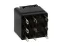
Chevrolet Tracker Flasher Relay Part Number: 30026596
$15.77 MSRP: $85.68You Save: $69.91 (82%)Ships in 1-2 Business Days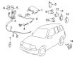
Chevrolet Tracker Flasher Relay Part Number: 30024283
$62.69 MSRP: $100.75You Save: $38.06 (38%)Ships in 1-2 Business Days
Chevrolet Tracker Turn Signal Flasher
Want to cut long-term maintenance and repair costs? Choose OEM Turn Signal Flasher. Those parts deliver top durability you can trust. On our site, you'll find a huge catalog of genuine Chevrolet Tracker parts. Prices are unbeatable, so you can keep more in your pocket. Every OEM Chevrolet Tracker Turn Signal Flasher includes a manufacturer's warranty. You can also get an easy return policy that keeps buying risk free. Fast delivery, get your car on the road quickly. It's simple to search, compare, and order. Stop guessing about quality or fit. Order today and save with parts that last.
Chevrolet Tracker Turn Signal Flasher Parts Questions & Experts Answers
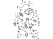
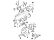
- Q: How to service and repair the turn signal flasher on Chevrolet Tracker?A:The first step to service or repair the Turn Signal Flasher requires disconnecting the negative Battery Cable. First detach the ip steering column opening trim plate to slide the bracket with Fuel Pump Relay and main relay out from the junction block's left-front position. Disconnect the following connectors from the bottom of the junction block : the service and repair process includes inline connector c213 and inline connector c205 and inline connector c204. Proceed with disconnecting junction block connector c4 followed by disconnection of junction block connector c5 from their front positions on the junction block. Use socket wrenches to unfasten the two junction block retaining nuts which secure it at the left hinge pillar and the bulkhead retaining nut before extracting the junction block. Unfasten the junction block from its three retaining studs to access rear electrical connectors for disconnecting. Release the connector housing from the junction block by easing the retaining tabs at the top section. You need to extract the turn/hazard flasher from the junction block by first disengaging each retaining tab then pulling it straight out. Installation requires the turn/hazard flasher to be inserted back into the junction block with retaining tabs extended completely. Place the connector housing back onto the junction block by aligning its retaining tabs at the top. Fasten the junction block to its 3 mounting studs by using the 3 corresponding nuts (3,10). Tighten each nut to a torque of 10 n.m (89 lb in). Start by attaching junction block connector c4 and c5 to the junction block front section followed by installing inline connectors c213, c205, c204 to the junction block bottom. Place the bracket with the Fuel Pump Relay and main relay at the left front side of junction block then replace the ip steering column opening trim plate before reconnecting the negative Battery Cable.

Related Chevrolet Tracker Parts
 Chevrolet Tracker ABS Relay
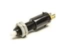 Chevrolet Tracker Brake Light Switch
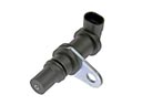 Chevrolet Tracker Crankshaft Position Sensor
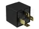 Chevrolet Tracker Daytime Running Light Relay
 Chevrolet Tracker Dimmer Switch
 Chevrolet Tracker Engine Control Module
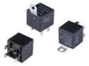 Chevrolet Tracker Fuel Pump Relay
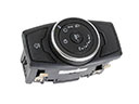 Chevrolet Tracker Headlight Switch
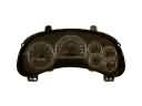 Chevrolet Tracker Instrument Cluster
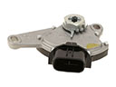 Chevrolet Tracker Neutral Safety Switch
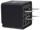 Chevrolet Tracker Relay
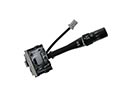 Chevrolet Tracker Wiper Switch