ChevyParts
My Garage
My Account
Cart
OEM Chevrolet Transfer Case
Speed Transfer Case- Select Vehicle by Model
- Select Vehicle by VIN
Select Vehicle by Model
orMake
Model
Year
Select Vehicle by VIN
For the most accurate results, select vehicle by your VIN (Vehicle Identification Number).
101 Transfer Cases found


Chevrolet Transfer Case Part Number: 19125650
$3037.53 MSRP: $3413.55You Save: $376.02 (12%)Ships in 1-3 Business DaysProduct Specifications- Other Name: Case, Transfer Case
- Replaces: 24243562, 24247208, 12587651, 24252681, 24250862

Chevrolet Transfer Case Part Number: 85580978
$1267.10 MSRP: $1415.08You Save: $147.98 (11%)Product Specifications- Other Name: Case Assembly-Transfer; Case, Transfer Case
- Replaced by: 85843422
Chevrolet Differential Case Part Number: 84640877
$81.64 MSRP: $127.88You Save: $46.24 (37%)Ships in 1-3 Business DaysProduct Specifications- Other Name: Case-Differential; Case,; Differential
- Replaces: 23490346
Chevrolet Transfer Case Part Number: 84636465
$190.88 MSRP: $300.26You Save: $109.38 (37%)Ships in 1-3 Business DaysProduct Specifications- Other Name: Case-Transfer; Case, Transfer Case; Case
- Replaces: 84467662
Chevrolet Transfer Case Part Number: 84844730
$748.30 MSRP: $1182.71You Save: $434.41 (37%)Ships in 1-3 Business DaysProduct Specifications- Other Name: Case Assembly-Power Transfer U
- Replaces: 84757524
Chevrolet Transfer Case Part Number: 15045746
$1036.12 MSRP: $1329.43You Save: $293.31 (23%)Ships in 1-3 Business DaysProduct Specifications- Replaces: 15733771

Chevrolet Transfer Case Part Number: 24236607
$2942.56 MSRP: $3306.60You Save: $364.04 (12%)Ships in 1-3 Business DaysProduct Specifications- Other Name: Case, Transfer Case
- Replaced by: 24228408
Chevrolet Transfer Case Part Number: 84619036
$1944.24 MSRP: $2182.36You Save: $238.12 (11%)Ships in 1-3 Business DaysProduct Specifications- Other Name: Case Assembly-Transfer
- Replaced by: 85675344
Chevrolet Transfer Case Part Number: 84993041
$796.82 MSRP: $897.32You Save: $100.50 (12%)Ships in 1-3 Business DaysProduct Specifications- Other Name: Case Assembly-Power Transfer U; Case, Transfer Case; Case
- Replaced by: 85835535
- Replaces: 84429007, 84332857, 84453401, 84370678, 84221087
Chevrolet Transfer Case Part Number: 84993040
$1061.26 MSRP: $1195.11You Save: $133.85 (12%)Ships in 1-3 Business DaysProduct Specifications- Other Name: Case Assembly-Power Transfer U
- Replaced by: 85732470
- Replaces: 84370677, 84429006, 85610357, 84453400, 84332856, 84104331, 84423966, 84221086

Chevrolet Transfer Case Part Number: 23188338
$3528.70 MSRP: $4017.20You Save: $488.50 (13%)Ships in 1-2 Business DaysProduct Specifications- Other Name: Case Assembly-Transfer; Case, Transfer Case
- Replaces: 24243564, 24256474, 24250864, 24247210, 24252683, 24261516, 24256219

Chevrolet Transfer Case Part Number: 24228420
$3074.14 MSRP: $3454.78You Save: $380.64 (12%)Ships in 1-3 Business DaysProduct Specifications- Other Name: Case, Transfer Case
- Replaces: 24239524
Chevrolet Transfer Case Part Number: 84370679
$1279.61 MSRP: $1441.00You Save: $161.39 (12%)Ships in 1-3 Business DaysProduct Specifications- Other Name: Case Assembly-Power Transfer U
- Replaced by: 84429008
Chevrolet Transfer Case Part Number: 24228408
$2942.56 MSRP: $3306.60You Save: $364.04 (12%)Ships in 1-3 Business DaysProduct Specifications- Other Name: Case, Transfer Case
- Replaces: 12580320, 12585316, 12585314, 12577425, 15155589, 12588508, 24242561, 24236607

Chevrolet Transfer Case Part Number: 24232827
$3137.95 MSRP: $3533.73You Save: $395.78 (12%)Ships in 1-3 Business DaysProduct Specifications- Other Name: Case, Transfer Case
- Replaces: 24231475

Chevrolet Transfer Case Part Number: 19125971
$3033.77 MSRP: $3409.31You Save: $375.54 (12%)Ships in 1-3 Business DaysProduct Specifications- Other Name: Case Assembly, Transfer (Remanufacture); Case, Transfer Case
- Replaces: 19125655, 24245992, 19125968, 24247213, 24252686, 24250865, 12578109
Chevrolet Transfer Case Part Number: 85580977
$1091.62 MSRP: $1217.47You Save: $125.85 (11%)Product Specifications- Other Name: Case Assembly-Transfer; Case, Transfer Case
- Replaced by: 85059483
Chevrolet Transfer Case Part Number: 23188339
Product Specifications- Other Name: Case, Transfer Case
- Replaces: 24261515, 24256218, 24256473
Chevrolet Transfer Case Part Number: 19125659
$3140.51 MSRP: $3529.52You Save: $389.01 (12%)Product Specifications- Other Name: Case, Transfer Case
- Replaces: 24252687, 24247214, 24243014, 24245993, 12578114

Chevrolet Transfer Case Part Number: 24251671
$3311.97 MSRP: $3729.71You Save: $417.74 (12%)Product Specifications- Other Name: Case, Transfer Case
- Replaces: 24240570, 24243641
| Page 1 of 6 |Next >
1-20 of 101 Results
Chevrolet Transfer Case
Choose OEM Transfer Case, you're making the optimal decision for superior quality and perfect performance. You can feel confident because each component goes through stringent quality checks. Every part is carefully built to comply with Chevrolet's factory specifications. You'll enjoy a smooth, worry-free installation that fits just right. At ChevyPartsGiant.com, you'll find it easy to get top-quality OEM Chevrolet Transfer Case. You can shop at highly competitive prices and protect your budget. All our genuine Chevrolet parts include a dependable manufacturer's warranty. You'll also appreciate our straightforward return policy and swift delivery services for extra convenience.
Chevrolet Transfer Case Parts and Q&A
- Q: What tools are necessary to disassemble the transfer case on Chevrolet Express 3500?A:Several tools needed to disassemble the Transfer Case include slide hammer (J 2619-01) and holding fixture (J 3289-20) and split plate bearing puller (J 22912-01) and slide hammer with bearing adapter (J 23907) and bushing and bearing remover - 3-4 inch (J 26941) and case spreader (J 45358) and mainshaft support bushing/bearing remover (J 45548). For Transfer Case disassembly you will require slide hammer (J 2619-01), holding fixture (J 3289-20), split plate bearing puller (J 22912-01), slide hammer with bearing adapter (J 23907) as well as bushing and bearing remover - 3-4 inch (J 26941) and case spreader (J 45358) and mainshaft support bushing/bearing remover (J 45548). Attach the assembly fixture (J 45759) to the Transfer Case through adapter studs for mounted case disassembly operations. Weld the assembly fixture (J 45759) to a holding fixture (J 3289-20) set up on a stable workbench before securing the stack with a pivot pin. The process to drain Transfer Case fluid requires removal of both drain and fill plugs. The procedure requires front output shaft seal removal followed by encoder motor assembly extraction and Vehicle Speed Sensor (VSS) removal and finally rear output shaft seal removal. Use the case spreader to shear the sealer between the case halves before removing the Transfer Case retaining bolts together with washers while noting down the brackets' original positions. Apply the case spreader (J 45358) to break the sealer binding between case halves before separating the front from the rear halves of the case. Remove sequentially the shift fork shaft spring together with the rear sun gear planetary Differential assembly and the chain containing drive and driven sprockets. You must mark how the chain and sprockets fit together to keep their wear patterns when reusing them. Attack the remaining components starting with the lockup shift assembly and progressing through the Oil Pump assembly before finally removing the shift detent lever assembly but maintain straight alignment of the shift detent lever shaft assembly throughout the process. To finish the task remove the mainshaft rear support bushing with slide hammer (J 2619-01) and mainshaft support bushing/bearing remover (J 45548) and use the bushing and bearing remover (J 26941) together with slide hammer with bearing adapter (J 23907) to eliminate the rear bearing for the front output shaft.
Related Chevrolet Parts
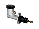 Chevrolet Clutch Master Cylinder
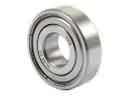 Chevrolet Pilot Bearing
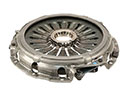 Chevrolet Pressure Plate
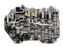 Chevrolet Valve Body
 Chevrolet Automatic Transmission Input Shaft Seal
 Chevrolet Automatic Transmission Seal
 Chevrolet Automatic Transmission Shift Levers
 Chevrolet Automatic Transmission Shifter
 Chevrolet Clutch Hose
 Chevrolet Release Bearing
 Chevrolet Transfer Case Seal
 Chevrolet Transmission Gasket
Browse Chevrolet Transfer Case by Models
S10 Colorado Tahoe Equinox Avalanche Silverado 1500 Silverado 2500 HD Suburban Traverse Blazer Tracker Trax Trailblazer Astro C1500 C2500 C3500 Express 1500 Express 2500 Express 3500 K1500 K2500 K3500 Silverado 2500 Venture Silverado 3500 Suburban 1500 Trailblazer EXT Avalanche 1500 Avalanche 2500 C1500 Suburban C2500 Suburban Captiva Sport K1500 Suburban K2500 Suburban Silverado 1500 Classic Silverado 1500 HD Silverado 1500 HD Classic Silverado 1500 LD Silverado 2500 HD Classic Silverado 3500 Classic Silverado 3500 HD Suburban 2500 Suburban 3500 HD