ChevyParts
My Garage
My Account
Cart
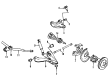
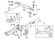
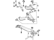
OEM GMC Sonoma Torsion Bar
Suspension Torsion Bar- Select Vehicle by Model
- Select Vehicle by VIN
Select Vehicle by Model
orMake
Model
Year
Select Vehicle by VIN
For the most accurate results, select vehicle by your VIN (Vehicle Identification Number).
8 Torsion Bars found


GMC Sonoma Torsion Bar, Front Driver Side Part Number: 15956503

GMC Sonoma Torsion Bar, Front Passenger Side Part Number: 15956510
GMC Sonoma Torsion Bar, Front Driver Side Part Number: 15956509
GMC Sonoma Torsion Bar, Front Passenger Side Part Number: 15956504
GMC Sonoma Torsion Bar, Front Passenger Side Part Number: 14056382
GMC Sonoma Torsion Bar, Front Driver Side Part Number: 14056381
GMC Sonoma Torsion Bar, Front Part Number: 14034282
GMC Sonoma Torsion Bar, Front Part Number: 14034281
GMC Sonoma Torsion Bar
Want to cut long-term maintenance and repair costs? Choose OEM Torsion Bar. Those parts deliver top durability you can trust. On our site, you'll find a huge catalog of genuine GMC Sonoma parts. Prices are unbeatable, so you can keep more in your pocket. Every OEM GMC Sonoma Torsion Bar includes a manufacturer's warranty. You can also get an easy return policy that keeps buying risk free. Fast delivery, get your car on the road quickly. It's simple to search, compare, and order. Stop guessing about quality or fit. Order today and save with parts that last.
GMC Sonoma Torsion Bar Parts Questions & Experts Answers
- Q: How to replace the torsion bar and support assembly on GMC Sonoma?A:To remove the Torsion Bar and supports assembly, raise and support the vehicle first. Mark the adjuster bolt and install the Torsion Bar loading/unloading tool (J 36202) to the adjustment arm and the crossmember. Enough to create a hand wrench, tighten it through the adjuster bolt, remember how many turns it takes for further reference. To remove the adjuster bolt and adjuster nut, then remove the Torsion Bar loading/unloading tool (J 36202) so that the Torsion Bar can unload. Shift the Torsion Bar to the front to take off the adjustment arm, then the upper mounting nuts and bolts of the Torsion Bar support link. Then discard bar support from the frame, and the torsion bars, being certain of the forward end and side of the dismissed bars. Replace the lower retaining nuts of the Torsion Bar links and disengage the links from the Torsion Bar support. For installation, affix the Torsion Bar links to Torsion Bar support and install lower retaining nuts tightening to 50 nm (37 ft lbs). Mount the torsion bars in the original places and place the Torsion Bar stand to the frame. Tighten the upper mounting bolts and nuts of the Torsion Bar support link for 65 nm (48 ft. Lbs). Mount the adjustment arm on the Torsion Bar support and push the Torsion Bar rearward till it is fully inside the adjustment arm. Mount the Torsion Bar loading/unloading tool (J 36202) back to the adjustment arm and crossmember, and put tension on the Torsion Bar by turning the adjuster bolt the same number of turns as in the removal. Finally, install the adjuster bolt and adjuster nut, remove the torsionbar loading/unloading tool (J 36202), drop the vehicle, and inspect the wheel alignment.

Related GMC Sonoma Parts
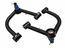 GMC Sonoma Control Arm
 GMC Sonoma Alignment Bolt
 GMC Sonoma Axle Beam Mount
 GMC Sonoma Axle Support Bushings
 GMC Sonoma Control Arm Bolt
 GMC Sonoma Control Arm Bumper
 GMC Sonoma Spindle
 GMC Sonoma Steering Knuckle
 GMC Sonoma Sway Bar Bracket
 GMC Sonoma Sway Bar Bushing
 GMC Sonoma Sway Bar Kit
 GMC Sonoma Sway Bar Link