
Popular OEM GMC Sonoma Parts
- Body & Hardware Parts View More >
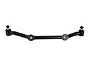
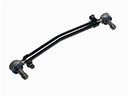
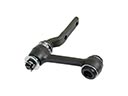
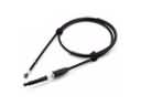
- Steering Parts View More >
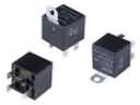
- Electrical Parts View More >
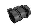
- Air & Fuel Delivery Parts View More >
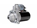
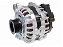
- Charging & Starting Parts View More >
- Engine Parts View More >
- Belts & Cooling Parts View More >
- Suspension Parts View More >
- Driveline & Axles Parts View More >
- Emission Control & Exhaust Parts View More >
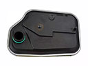
- Transmission Parts View More >
- Brakes Parts View More >


Why Buy Genuine GMC Sonoma Parts From ChevyPartsGiant.com
Looking for real GMC Sonoma parts? ChevyPartsGiant.com may be a better choice to find genuine parts at wallet-friendly prices. We sell only OEM GMC Sonoma parts, ensuring perfect fit, reliability, and long-term performance. With our website, you can easily get access to the same parts found at local GMC stores. All components are produced by GMC and are exclusively fitted on GMC Sonoma automobiles. By shopping at our store, you can enjoy the quality of the GMC factory without the high prices of brick-and-mortar facilities. We achieve this because we are an online store operating at lower costs, which we pass on to you. We also have a user-friendly platform where you can find and order genuine GMC Sonoma parts swiftly. We are here to make your process of restoring a GMC Sonoma or dealing with simple repairs quick and inexpensive. We also make it easy to obtain GMC Sonoma parts at competitive shipping prices and a team of knowledgeable staff ready to take your order. Choose ChevyPartsGiant.com to save time and money, as well as keep your GMC Sonoma in the good condition.
The GMC Sonoma nameplate made its debut in 1991 as an updated designation for the GMC S-15 which had been available since 1982 as part of GM's compact pickup segment. Production of the second generation Sonoma started in 1994 when the vehicle added substantial improvements by using R134a CFC-free refrigerant for all air-conditioned models to meet Clean Air Act standards. Throughout its production period GMC Sonoma delivered multiple engine options such as the 2.2-liter inline-four and the 4.3-liter V6 engine which reached 190 horsepower in select models. The Sonoma vehicle utilized both front-engine rear-wheel-drive and optional four-wheel-drive layouts to ensure reliable traction and control on diverse terrain. Both manual and automatic gearboxes were available in the vehicle which delivered smooth transmissions and enhanced fuel efficiency. The GMC Sonoma combines a light-duty truck chassis with an enclosed passenger area and an open cargo space to serve both business and recreational needs. Authentic GMC Sonoma components are available to the market because they maintain peak performance alongside durable construction through strict manufacturer guidelines. The Sonoma maintains its reliability track record because its parts utilize premium-grade components produced through standardized official production methods. Advanced engineering techniques together with quality components enable the GMC Sonoma to serve various driving requirements.
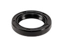
GMC Sonoma concerns group into fuel measurement, engine sealing, and cabin heating. In measuring fuel, the Sonoma tends to give a jittery gauge and an inaccurate reading range. The sensor of a failing fuel level within the module distorts the readings. Check scan data with cluster values, check grounds, and renew the fuel pump and sensor, as necessary. The intake gasket is the common part that fails in engine sealing in the GMC Sonoma. Symptoms are loss of coolant, milky oil, rough idle, and an increase in temperature during idle. Test the system pressure, crossover passages, and then re-fasten the intake manifold gasket and retorque respectively. On the GMC Sonoma, there is a possibility of leakage of coolant through the heater core on the passenger floor because of cabin heating. Smell inside the rear seat and under the carpet, look for a sweet odor and wet carpet. Replace the heater core and check hose routing. When repaired, the Sonoma is expected to start cleanly, maintain temperature, and provide consistent heat. Finish with a road test, clear codes, and recheck for leaks or gauge drift. Measure record pressures, voltages, and trim values so future GMC diagnostics can be efficient. Check temperature of the Sonoma again after hot soak to ensure a steady level of fuel showing.
GMC Sonoma Parts Questions & Answers
- Q: How to Replace an Interior Front Door Handle on GMC Sonoma?A:A person must first uninstall the door trim panel when replacing the front door interior handle. First remove the handle retaining bolt while sliding the handle forward until the handle locator tab frees from its cutout. Start by unlocking the rod retainer locks and extracting the rods from the handle until you can take out the handle from the door. Position the handle on the door before installing the rods to the handle and finally tightening the rod retainer locks. After placing the handle locator tab into the locator cutout you should move the handle toward the rear until the fastener hole properly lines up with the door. Reinstall the door trim panel after inserting the handle retaining bolt which must be tightened to 10 N.m (88 lb in).
- Q: How to replace the Heated Oxygen Sensor (HO2S) Bank 1 Sensor 2 on GMC Sonoma?A:You need to lift the vehicle before proceeding with HO2S Bank 1 Sensor 2 replacement. Remove the connector that connects to the HO2S. The HO2S should be removed using the Oxygen Sensor Wrench (J 39194-B). The new oxygen sensor threads must receive a coating of anti-seize compound GM P/N 5613695 followed by its installation. GM P/N 5613695 contains both liquid graphite and glass beads to make removal easier. The HO2S requires installation using the Oxygen Sensor Wrench (J 39194-B) until it reaches a torque value of 42 N.m (31 lb ft). Lastly connect the HO2S harness connector while lowering the vehicle.
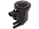
- Q: How to replace the lower intake manifold on GMC Sonoma?A:First dis-connect the neg. Battery cable and the breather tube at air cleaner outlet duct.then remove the air cleaner outlet duct to replace the lower Intake Manifold. Defeat the accelerator cable from the Throttle Body and keep it away from accelerator control cable bracket and followed by defeating the cruise control cable from throttle shaft and accelerator cable as well, if there's one. Remove the vacuum hose at the Intake Manifold if a/c is equipped, the power Brake Booster Vacuum Hose, and drain the cooling system. Disconnect the radiator inlet hose, hose leading to heater, and water pump inlet hose from the Intake Manifold. Cease the electrical connectors for fuel meter body assembly , evap canister purge solenoid valve,mapview sensor (MAP), ignition coil, ignition control module (ICM),generator, idle air control ( IAC ) motor, throttle position ( TP ) sensor, a/c compressor cutoff switch, a/c clutch switch, and engine coolant temperature ( ECT ) sensor. Cease the engine wiring harness clips and move the harness away and remove the accelerator cable bracket from the Throttle Body and Intake Manifold whiles keeping the cables connected. The pcv hose assembly must be removed from the Intake Manifold and valve rocker-arm cover, the evap canister purge solenoid valve and the Distributor. Remove the fuel supply and return hoses at the back of the Intake Manifold while avoiding the release of the refrigerant. To get access for left front bolt to the Intake Manifold, remove the Drive Belt, loosen and remove the power steering pump rear bracket nuts, and slide the power steering pump bracket front. Unplug the ect sensor wire connector, if available, and then unbolt the lower Intake Manifold bolts and Intake Manifold assembly, and dispose of the lower Intake Manifold gaskets. Clean the lower Intake Manifold with the cleaning solvent and dry it by compressed air checking on gasket sealing surfaces for damage or restricted cooling passages, cracks or damage to threading bolt holes. If a replacement was needed, use gm 4.0 mm (0.157 inch) patch of adhesive gm p/n 12346141 (Canadian P/N 10953433) or equivalent to the side of the Cylinder Head of the lower Intake Manifold gasket on each side, must be installed while the adhesive is still wet. Mount the lower Intake Manifold gasket on Cylinder Head using the gasket locator pins; apply a 5mm (0.197 inch) bead of adhesive gm p/n 12346141 (Canadian P/N 10953433) to the front and rear top of the engine block with bead running onto each lower Intake Manifold gasket. Mount the lower Intake Manifold on to the engine block and if bolts are re-used use thread lock gm p/n 12345382 (Canadian P/N 10953433) on the bolt heads, then tighten the bolts according to a predetermined sequence in a three-step sequence up to the specified torque values. Mount and loosely install power steering pump mounting bracket and tighten bolts and nuts at 41 nm (30 ft.blbs) and reinstall Drive Belt. Install the supply and return pipes of fuel while ensuring that the engine is at number one cylinder top dead center for fixing the Distributor. Remove the Spark Plug from the number one cylinder, turn Crankshaft to stop on the compression stroke, align the marks of reference, and re-install the Spark Plug and the Distributor. Replace the evap canister purge solenoid valve, pcv hose assembly, accelerator and cruise control cable bracket, tightening the nuts to specified torque values. Mount the engine wiring harness, attach the clips, and attach necessary electrical connectors. Attach the vacuum hose to the power brake booster, vacuum hose to the Intake Manifold if you have an a/c, and reinstall the water pump inlet hose, heater hose, and radiator inlet hose. If the vehicle comes with a cruise control cable, reinstall this particular cable, and then reinstall a cable that controls the accelerator on the Throttle Body making sure it is seated well, and attach the accelerator cable to the control bracket. Lastly, replace the air cleaner outlet duct, reconnect the breather tube, refill the cooling system, and reconnect the negative Battery Cable.
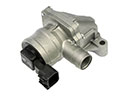
- Q: How to replace the throttle body assembly on GMC Sonoma?A:In order to replace the Throttle Body assembly, the mechanic has to disconnect the negative Battery Cable, remove the air cleaner outlet duct, and the air cleaner adapter stud. Release the cruise control cable and the accelerator cable from the Throttle Body and remove the nuts to hold the accelerator cable routing bracket which will be set aside. Next, you remove the stud and nuts holding the accelerator control cable bracket in place and take it off as well. Remove the iac valve harness connector and the throttle position (TP) sensor harness connector and then the Throttle Body was removed from their retaining studs and the Throttle Body itself was discarded along with the Throttle Body seal. Clean the surface of the Intake Manifold's seal and fit the Throttle Body assembly with new seal, holding it in place tightly with the retaining studs at 9 n.m (80 lb in). Insert and tighten the mounting stud and nuts to 12 n.m (106 lb in) and accelerator cable routing bracket nuts to 9 n.m (80 lb in). Check the full range of accelerator pedal movement to ensure the throttle runs freely without binding. Fit the accelerator cable and cruise control cable to the Throttle Body, and fit the tp sensor and iac valve harness connectors. Replace the air cleaner adapter stud with an 8 n.m (71 lb in) torque and the outlet duct of the air cleaner. Lastly, test the accelerator pedal operation by turning on the key with the engine out enabling a scan tool to check the tp sensor parameter and checking the movement of the throttle position from 0-100 percent and back to 0 percent.


