ChevyParts
My Garage
My Account
Cart
OEM GMC Yukon XL 1500 Evaporator
A/C Evaporator Core- Select Vehicle by Model
- Select Vehicle by VIN
Select Vehicle by Model
orMake
Model
Year
Select Vehicle by VIN
For the most accurate results, select vehicle by your VIN (Vehicle Identification Number).
4 Evaporators found


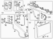
GMC Yukon XL 1500 Evaporator Core Part Number: 89019027
$213.23 MSRP: $438.18You Save: $224.95 (52%)Ships in 1-2 Business Days

GMC Yukon XL 1500 Evaporator Core Part Number: 89018270
$190.22 MSRP: $390.90You Save: $200.68 (52%)Ships in 1-2 Business Days


GMC Yukon XL 1500 Evaporator Core Part Number: 15225889
$119.45 MSRP: $353.58You Save: $234.13 (67%)Ships in 1-2 Business Days

GMC Yukon XL 1500 Evaporator Core Part Number: 89019057
GMC Yukon XL 1500 Evaporator
Want to cut long-term maintenance and repair costs? Choose OEM Evaporator. Those parts deliver top durability you can trust. On our site, you'll find a huge catalog of genuine GMC Yukon XL 1500 parts. Prices are unbeatable, so you can keep more in your pocket. Every OEM GMC Yukon XL 1500 Evaporator includes a manufacturer's warranty. You can also get an easy return policy that keeps buying risk free. Fast delivery, get your car on the road quickly. It's simple to search, compare, and order. Stop guessing about quality or fit. Order today and save with parts that last.
GMC Yukon XL 1500 Evaporator Parts Questions & Experts Answers
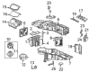
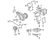
- Q: How to replace the evaporator core in the auxiliary HVAC module on GMC Yukon XL 1500?A:Before starting Evaporator core replacement on the auxiliary hvac module, technicians should recover a/c system refrigerant and drain engine coolant. Begin by raising the vehicle and disconnecting the heater lines from the auxiliary hvac module that is located underneath the vehicle. Then follow this step with removing the air conditioning lines from the same module. Unscrew the nuts holding the auxiliary hvac module to the vehicle structure after which you can remove safety stands from under the vehicle where you can lower it to the ground. You should start by removing the right rear quarter trim panel along with the real time damping (RTD) module then disconnect all electrical connectors when necessary. Proceed by disassembling the fasteners from the upper auxiliary air duct and lower auxiliary outlet duct and air distributor duct before extracting the rear auxiliary hvac module to work on a stable surface. Disassemble the air temperature actuator alongside the stud connecting Heater Core input and output pipes followed by skilled detachment of the module case gasket from the Heater Core pipes. Next separate the Heater Core from the clamp and rear hvac module lower cover after keeping the existing gasket available for reuse. The installer separates the front case from the back half and removes the Evaporator core from the back section for gasket and seal evaluation with necessary replacements. The assembling process includes moving the thermal expansion valve (TXV) to the new Evaporator core then installing both components with the Evaporator core seal while ensuring correct placement of air distributor duct gasket and temperature door during this operation. Case halves should be put together while also connecting the Heater Core and managing its clamp and the rear hvac module lower cover. After securing both bolts the vehicle receives the auxiliary hvac module, air temperature actuator and Heater Core pipe retainer and gasket and stud. Reassemble the air distributor duct and the lower auxiliary air outlet together with the upper auxiliary air duct by joining electrical connectors and rtd module. The vehicle needs to be raised for securing the auxiliary hvac module through the use of nuts which require a torque of 9 n.m (80 lb in). Link the air conditioning connectors followed by tightening the nut to 16 n.m (12 lb ft), then resume heater line operation. Proceed with fitting engine coolant before recharging the refrigerant then perform fitting leak detection with the halogen leak detector (J 39400-A).

Related GMC Yukon XL 1500 Parts
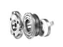 GMC Yukon XL 1500 A/C Clutch
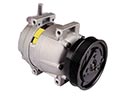 GMC Yukon XL 1500 A/C Compressor
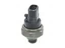 GMC Yukon XL 1500 A/C Compressor Cut-Out Switches
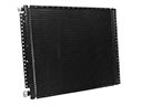 GMC Yukon XL 1500 A/C Condenser
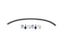 GMC Yukon XL 1500 A/C Hose
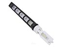 GMC Yukon XL 1500 A/C Orifice Tube
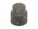 GMC Yukon XL 1500 A/C Service Cap
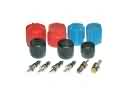 GMC Yukon XL 1500 A/C System Valve Core
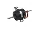 GMC Yukon XL 1500 Blower Motor
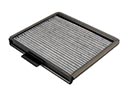 GMC Yukon XL 1500 Cabin Air Filter
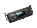 GMC Yukon XL 1500 HVAC Control Module
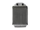 GMC Yukon XL 1500 Heater Core