
Popular OEM GMC Yukon XL 1500 Parts
- Body & Hardware Parts View More >
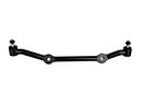
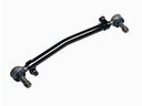
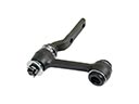
- Steering Parts View More >
- Electrical Parts View More >
- Air & Fuel Delivery Parts View More >
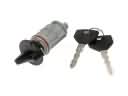
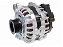
- Charging & Starting Parts View More >
- Engine Parts View More >
- Belts & Cooling Parts View More >
- Suspension Parts View More >
- Driveline & Axles Parts View More >
- Emission Control & Exhaust Parts View More >
- Transmission Parts View More >
- Brakes Parts View More >

Why Buy Genuine GMC Yukon XL 1500 Parts From ChevyPartsGiant.com
Looking for real GMC Yukon XL 1500 parts? ChevyPartsGiant.com may be a better choice to find genuine parts at wallet-friendly prices. We sell only OEM GMC Yukon XL 1500 parts, ensuring perfect fit, reliability, and long-term performance. With our website, you can easily get access to the same parts found at local GMC stores. All components are produced by GMC and are exclusively fitted on GMC Yukon XL 1500 automobiles. By shopping at our store, you can enjoy the quality of the GMC factory without the high prices of brick-and-mortar facilities. We achieve this because we are an online store operating at lower costs, which we pass on to you. We also have a user-friendly platform where you can find and order genuine GMC Yukon XL 1500 parts swiftly. We are here to make your process of restoring a GMC Yukon XL 1500 or dealing with simple repairs quick and inexpensive. We also make it easy to obtain GMC Yukon XL 1500 parts at competitive shipping prices and a team of knowledgeable staff ready to take your order. Choose ChevyPartsGiant.com to save time and money, as well as keep your GMC Yukon XL 1500 in the good condition.
Since 2000 the GMC Yukon XL 1500 has developed into a million-pound SUV which performs well on streets and handles basic off-road situations. The GMT800-based Yukon XL 1500 arrived in 2000 to the market by offering enhanced handling and structural strength and increased towing potential beyond the Suburban. The original GMC Yukon XL 1500 entered the market with a 5.3L V8 Vortec powerplant delivering 285 horsepower thus providing enhanced efficiency and performance than the discontinued 5.7L V8. The introduction of the 6.0L V8 engine brought aluminum cylinder heads that raised horsepower production by 20 units. A GMC Yukon XL 1500 series vehicle uses automatic transmission for smooth shifts and better driving performance. The GMC Yukon XL 1500 utilizes a complete four-wheel drive system which enables drivers to choose full-wheel entry or rear-wheel entry according to weather needs for improved traction control. The vehicle upgrades its brake parts alongside stronger axle systems for heavier towing functions with no loss of stability during operation. The GMC Yukon XL 1500 gained an interior revamp that accomplished comfort along with functionality by adding new instrument displays that offered information. Genuine OEM parts serve as an essential factor to preserve the GMC Yukon XL 1500's performance because GM's strict quality criteria keep both the operational excellence and extended lifespan of the vehicle.
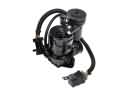
GMC Yukon XL 1500 addresses group into exhaust noise control, air conditioning drive, and evaporative sealing. The loose exhaust heat shield on the Yukon XL 1500 exhaust system pops off when expanding. Check clamps and spot welds, and replace the new kit or fasten the shield. Rattling tensioner and poor cooling are some HVAC drive issues on Yukon XL 1500. The cause is usually a worn-out AC compressor with an irregular loading of the belt. Confirm pressures and clutch command, replace the AC compressor, and recheck. A lamp is usually flagged by evaporation sealing on the Yukon XL 1500 when it is refueled. An old gas cap cannot maintain a vacuum and leaks late. Check the cap seal, smoke test lines, clear codes, and check monitors on the Yukon XL 1500. The Yukon XL 1500 should remain silent, cool, and pass readiness after repairs. Follow GMC procedures for torque and seal checks, and document results for future GMC service. Check the GMC scan data to verify that there is a stable clutch engagement and EVAP performance. In the process of diagnosis, track GMC torque values and re-check clamps between heat cycles.
GMC Yukon XL 1500 Parts Questions & Answers
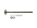
- Q: How to replace a one-piece Drive Shaft on GMC Yukon XL 1500?A:The replacement of a one-piece propeller shaft requires you to measure all driveline components relative to the propeller shaft and axles before disassembly for the propeller shafts, drive axles, pinion flanges, and output shafts including reference marking operations to preserve their original relationships. The first step involves lifting the vehicle during which you should mark the propeller shaft to match the pinion yoke of the rear axle and the transmission or Transfer Case. The rear axle pinion yoke requires removal of its retaining bolts before its yoke retainers can come out. The yoke ears alongside Universal Joint should remain free from damage because both hitting them with tools or applying force directly will break the injection joints. The skilled installer should first move the propeller shaft in the forward position to eliminate the front connection between the rear axle pinion yoke before shifting it to the rear position for disconnection from transmission or Transfer Case before the vehicle receives its final shaft removal. Check if the Slip Yoke splines have enough grease before installation; if not present, use gm p/n 12345879 or equivalent grease as specified in 2w/d w/ a. T. Only. Only). The propeller shaft installation requires alignment of reference marks from removal before building a connection between the transmission or Transfer Case and the rear axle pinion yoke. During this step normalize the reference marks alignment. Put the yoke retainers into place followed by their bolts , tight them with 25 nm (19 ft. Lbs.) torque then restore the vehicle to the ground.
- Q: How to replace the emblem or nameplate on GMC Yukon XL 1500?A:Before installing the new emblem work on a clean surface that is free of debris particles. First use flash naphtha or an IPA and water mixture to wipe and dry the surface where you will mount the new emblem. Control the body parts at 27-41°C (80-105°F) and adjust them when needed while managing the emblem temperature between 29-32°C (80-90°F) using minimal heat application. Take off the protective covering from the emblem. Press appliques onto the body with 3-10 lb force and follow it with 0.005 inch thick clear plastic to activate 75% of the adhesive using high pressure. Include all emblem pieces on their designated spots before pressing them hard to achieve full vehicle attachment.
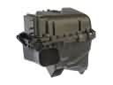
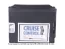
- Q: How to remove the intake manifold on GMC Yukon XL 1500?A:Removing the Intake Manifold starts by removing the engine sight shield and retainer followed by fuel system pressure relief. First disconnect the cruise control cable from the throttle blade stud before removing it from the bracket and then remove the accelerator control cable from the throttle blade and its bracket. The procedure continues by disconnecting the Fuel Rail's main ignition coil harness and fuel injectors while also removing the harness clips. You should next proceed to uninstall the main ignition coil harness and fuel injectors while also disconnecting the exhaust gas recirculation (EGR) valve. Lastly remove the harness clips that secure the Fuel Rail. Fasten the Knock Sensor harness electrical connector to the Intake Manifold while you disconnect the manifold absolute pressure (MAP) sensor and Knock Sensor. Set the electrical harness to the side. Connectors should first be removed from the throttle position (TP) sensor if present before proceeding to disconnect the electronic throttle control (ETC) motor if present and the idle air control (IAC) valve and purge solenoid then generator . Remove the wiring harness bracket nut and its bracket attachment at the stud before readjusting the engine wiring harness alongside the coolant air bleed hose at the Throttle Body. Ensure the Throttle Body remains hose-free during this process. Remove the radiator vent inlet hose from the Throttle Body by removing its clamp. The positive crankcase ventilation (PVC) hose needs to be taken from the Throttle Body and rocker arm cover and the pcv hose (with valve) needs to be taken from the Intake Manifold and rocker arm cover. The egr pipe bolts need removal from three points: Intake Manifold and Cylinder Head and Exhaust Manifold. The egr pipe (with valve) and Exhaust Manifold gasket must also be extracted. Remove the vacuum brake booster hose from the rear of the Intake Manifold when equipment requires it. You need to first disconnect the evaporative emission (EVAP) purge solenoid vent tube from its solenoid section while pressing the evap pipe fastener to separate the tube end from the vapor pipe. Begin by disconnecting the fuel line quick connect fittings before you remove the bolts from the Intake Manifold and its adjoining gaskets which must be discarded. Wipe down both the gasket surfaces on the egr pipe and the Exhaust Manifold for cleanup. The Throttle Body and Fuel Rail with injectors must be removed along with the MAP Sensor along with the accelerator control cable bracket bolts and bracket and the evap solenoid bolt and solenoid and isolator when replacing the Intake Manifold.
- Q: How to replace the rear door handle on GMC Yukon XL 1500?A:The procedure for exterior handle replacement starts with removing the trim panel followed by pulling back the water deflector depending on the circumstances. You need to detach the lock cylinder rod from its rod clip before removing the nuts on the outside handle and taking out the handle itself. You should disconnect electrical cables and take off the Door Lock Cylinder while removing the actuator cable. Handle lock cylinder binding requires proper attention while new cylinder lock coding needs correct procedures. You should apply gm p/n 12345120 (Canadian P/N 726548) lubricant inside the lock case and keyway of the cylinder during new lock cylinder installation. To complete the door lock repair you must install the Door Lock Cylinder together with the actuator cable before connecting the electrical connector if present followed by handle assembly installation. Move on to tighten the outside handle mounting nuts to 9 n.m (80 lb in), install the lock cylinder rod within the rod clip and reinstall the required water deflector as well as trim panel.


