
Popular OEM GMC C3500 Parts
- Body & Hardware Parts View More >
- Steering Parts View More >
- Electrical Parts View More >
- Air & Fuel Delivery Parts View More >
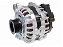
- Charging & Starting Parts View More >
- Engine Parts View More >
- Belts & Cooling Parts View More >
- Suspension Parts View More >
- Driveline & Axles Parts View More >
- Emission Control & Exhaust Parts View More >
- Transmission Parts View More >
- Brakes Parts View More >

Why Buy Genuine GMC C3500 Parts From ChevyPartsGiant.com
Looking for real GMC C3500 parts? ChevyPartsGiant.com may be a better choice to find genuine parts at wallet-friendly prices. We sell only OEM GMC C3500 parts, ensuring perfect fit, reliability, and long-term performance. With our website, you can easily get access to the same parts found at local GMC stores. All components are produced by GMC and are exclusively fitted on GMC C3500 automobiles. By shopping at our store, you can enjoy the quality of the GMC factory without the high prices of brick-and-mortar facilities. We achieve this because we are an online store operating at lower costs, which we pass on to you. We also have a user-friendly platform where you can find and order genuine GMC C3500 parts swiftly. We are here to make your process of restoring a GMC C3500 or dealing with simple repairs quick and inexpensive. We also make it easy to obtain GMC C3500 parts at competitive shipping prices and a team of knowledgeable staff ready to take your order. Choose ChevyPartsGiant.com to save time and money, as well as keep your GMC C3500 in the good condition.
General Motors manufactured the GMC C3500 as a key model of its fourth-generation C/K pickup truck sequence from 1988 to 2000 during which time it underwent substantial engineering transformation. The GMC C3500 builds upon GM GMT400 framework to offer various body types as 2 and 4 doors while reaching one ton maximum payload weight. The vehicle started with five engine options but finished with a 6.5-liter turbodiesel V8 which added torque for increased efficiency to its lineup. The transmission system received electronic control updates on the 700R4 which improved shifting logistics and vehicle dynamic control starting from 1993. The GMC C3500 Suburban maintains 131 inches for its wheelbase while offering a length measurement of 220 inches which results in excellent stability throughout work and leisure activities. The GMC C3500 production received updates including composite headlamps in 1990 while the vehicle gained passenger-side airbags for safety during 1997 manufacturing. Using original equipment manufacturer GMC C3500 parts remains essential because it ensures both the durability of the vehicle and its peak performance as part of GMC's quality standards.
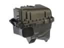
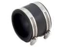
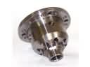
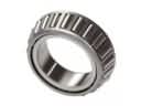
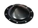
GMC C3500 groups concerns into engine sealing, rear axle lubrication, and cabin cooling. In the engine group, the C3500 may lose coolant and stumble on cold starts. A tired intake manifold gasket seeps internally or externally, raising misfire risk. Pressure test, inspect edges, then install updated gaskets and apply correct torque. Bleed the cooling system, confirm steady level, and recheck cold start quality on the C3500. For the drivetrain, the GMC C3500 can sling gear oil onto wheels or brake drums. Leaks at the axle hub or pinion seal reduce lubrication and invite bearing damage. Clean the housing, set preload, verify backlash, and replace leaking seals on the C3500. Check vent operation, a clogged vent raises case pressure and restarts seepage. In HVAC, the C3500 may cool weakly and leave oily residue. A worn A/C compressor or a cracked A/C condenser lowers capacity and contaminates refrigerant. Recover the charge, replace faulty components, evacuate deeply, and recharge to label specification. After repairs, road test the GMC on smooth pavement and hills. Verify coolant stability, axle temperature, and vent temperatures. Document measurements so GMC C3500 service remains traceable and predictable.
GMC C3500 Parts Questions & Answers
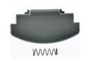
- Q: How to replace the rear side door handle on GMC C3500?A:The first step to replace the rear side door outside handle is removing both the trim panel along with the water deflector. First detach the handle control rod from the clip retainer by removing the handle mounting bolts before separating the outside handle from the door. The installation method starts with attaching the handle control rod to the handle clip retainer. Before installing the cylinder lock replace the inside of the lock case and keyway with GM P/N 12345120 lubricant or another suitable product. Before performing the installation place the handle assembly upside down and insert the handle control rod through the hole of the lock then right the assembly upright. You should first tighten the 4 N.m (35 lb in) mounted bolts on the outside handle then add the water deflector and conclude with the trim panel installation.
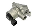
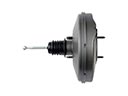
- Q: How to replace the vacuum brake booster on GMC C3500?A:First, take out the negative Battery Cable and then engage the park brake before replacing the vacuum Brake Booster. Remove the nuts that hold the master cylinder and then pull out the master cylinder and bracket. Start by removing the hose and the retainer, then the stoplamp switch and Pushrod and finish by taking out the assembly and the gasket by removing four nuts. The first step is to place the gasket, then the booster assembly and tighten the four nuts to 36 nm (26 ft. Lbs.). After that, fit the Pushrod, stoplamp switch and retainer and finally the vacuum hose. After checking the booster Pushrod, put in the master cylinder and bracket while fastening the master cylinder nuts with 30 nm (20 ft. Lbs.) torque. After that, let go of the park brake and join the negative cable to the battery again.
- Q: How to replace the left exhaust manifold on GMC C3500?A:To remove the left Exhaust Manifold remove the Exhaust Pipe from Exhaust Manifold, disconnect the Oxygen Sensor electrical connector and egr valve pipe from Exhaust Manifold. Then unscrew the Exhaust Manifold bolts and remove the Exhaust Manifold making sure to clean all sealing surfaces. To install, place the Exhaust Manifold and attach egr valve pipe to it then tighten the egr valve pipe nut. Lastly add the Exhaust Pipe to the Exhaust Manifold while observing the necessary precautions for fasteners.
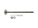
- Q: How to replace a three-piece Drive Shaft on GMC C3500?A:The maintenance of three-piece propeller shaft begins with hoisting the vehicle and creating exact reference marks between driveline parts and propeller shaft and axles before dismantling the assembly. This process allows precise reassembly of components to maintain their original positions. Start by making marks on the pinion flange-rear propeller shaft interface and then support the shaft before unscrewing the bolts from the pinion flange followed by the retainers. It is essential to avoid hitting the original propeller shaft yoke ears with a hammer because this may cause fractures and you should attach tape to the bearing cups on the yoke to hold the rollers in place. You should keep the Universal Joint assembly straight when you slide down the rear propeller shaft without the pinion flange assembly. First support the intermediate propeller shaft then remove the bolts at the front center bearing support of the front propeller shaft yoke together with the yoke retainers followed by removing the intermediate shaft center bearing support nuts and retainers. After removing the bolts accompanied by washers you can pull out the intermediate propeller shaft center bearing support from the hanger but always maintain the integrity of the yoke ears. Shorten and support the front propeller shaft while removing its bolts and retainers from the yoke before proceeding to detach the center bearing support nuts and bolts and washers. An approved solvent should be used to clean all parts before inspecting the proper installation of Universal Joint bearing cups and the intermediate and rear propeller shaft slip yoke splines. Also inspect rubber insulators for deterioration. You should attach the front propeller shaft to its yoke and verify reference marks are properly situated before bolt and retainer installation at 20 nm (26 ft. Lbs.). Join the intermediate propeller shaft with the front propeller shaft yoke while keeping them focused in proper alignment before tightening the bolts and retainers to 35 nm (26 ft. Lbs.). The rear center bearing hanger needs installation perpendicular to front and intermediate propeller shaft center lines before a thorough inspection of installed components. Use bolts and washers before supporting the rear propeller shaft with appropriate tools to tighten the nuts to 35 nm (26 ft. Lbs.). Align reference marks during the installation of rear propeller shaft bolts and retainers which should be tightened to 37 nm (27 ft. Lbs.).


