ChevyParts
My Garage
My Account
Cart
OEM 2001 Buick Park Avenue Control Arm
Suspension Arm- Select Vehicle by Model
- Select Vehicle by VIN
Select Vehicle by Model
orMake
Model
Year
Select Vehicle by VIN
For the most accurate results, select vehicle by your VIN (Vehicle Identification Number).
4 Control Arms found


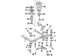
2001 Buick Park Avenue Control Arm, Driver Side Part Number: 25766511
$195.81 MSRP: $317.79You Save: $121.98 (39%)Product Specifications- Other Name: Arm, Steering Knuckle Upper & Lower Control; Suspension Control Arm and Ball Joint Assembly; Control Arm Assembly; Lower Control Arm; Arm, Steering Knuckle Lower Control
- Position: Driver Side
- Replaces: 25699467, 25703055, 25672870, 25696334, 88967801, 25766508, 25746324, 88986632, 25702221, 25745395
- Item Weight: 8.50 Pounds
- Item Dimensions: 18.8 x 16.1 x 4.4 inches
- Condition: New
- Fitment Type: Direct Replacement
- SKU: 25766511
- Warranty: This genuine part is guaranteed by GM's factory warranty.

2001 Buick Park Avenue Control Arm, Passenger Side Part Number: 25766510
$195.81 MSRP: $317.79You Save: $121.98 (39%)Product Specifications- Other Name: Arm, Steering Knuckle Upper & Lower Control; Suspension Control Arm and Ball Joint Assembly; Control Arm Assembly; Lower Control Arm; Arm, Steering Knuckle Lower Control
- Position: Passenger Side
- Replaces: 19202594, 25696335, 25766509, 25672871, 88986633, 25746325, 25702222, 25703056, 25699468
- Item Weight: 8.40 Pounds
- Item Dimensions: 19.3 x 16.2 x 4.3 inches
- Condition: New
- Fitment Type: Direct Replacement
- SKU: 25766510
- Warranty: This genuine part is guaranteed by GM's factory warranty.


 Product Specifications
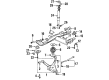
- Other Name: Arm Assembly-Rear Suspension Control; Lower Control Arm; Arm, Rear Axle Control Arm
- Position: Rear Passenger Side
- Replaces: 15897790, 25771881
- Item Weight: 17.30 Pounds
- Item Dimensions: 28.4 x 21.7 x 7.7 inches
- Condition: New
- Fitment Type: Direct Replacement
- SKU: 25820033
- Warranty: This genuine part is guaranteed by GM's factory warranty.


 Product Specifications
- Other Name: Arm Assembly-Rear Suspension Control; Lower Control Arm; Arm, Rear Axle Control Arm
- Position: Rear Driver Side
- Replaces: 15897788, 25626733, 25743300, 25675172, 25690655, 25765590, 25699091, 25628897
- Item Weight: 16.80 Pounds
- Item Dimensions: 31.2 x 22.1 x 8.2 inches
- Condition: New
- Fitment Type: Direct Replacement
- SKU: 25820031
- Warranty: This genuine part is guaranteed by GM's factory warranty.
2001 Buick Park Avenue Control Arm
With a comprehensive array of OEM 2001 Buick Park Avenue Control Arm, from fuel pumps to door handles, our website is a one-stop-shop for your needs. All our genuine 2001 Buick Park Avenue Control Arm are backed by the manufacturer's warranty and are offered at competitive prices in the market. Rest assured, you can shop with complete confidence.
2001 Buick Park Avenue Control Arm Parts and Q&A
- Q: How to service and repair the rear lower control arm on 2001 Buick Park Avenue?A: Coffingpc the rear suspension support assembly first; this will allow you to service and repair the rear lower Control Arm then. Then, unlink the automatic level control height sensor link that is located on the left Control Arm and disconnect the stabilizer shaft link. Then, go ahead and remove the wheel bearing/hub as well as the adjustment link retaining nut and the adjustment link from the lower Control Arm. Lug nuts and bolts on the lower Control Arm must be removed, then this arm would be pulled out. For installation, fix the lower Control Arm to rear suspension support assembly and be ensured of fixating the lower Control Arm nuts to the beams without the support of the vehicle with wheels at normal trim height. Put on the lower Control Arm bolts and nuts and reinstall the wheel bearing/hub. Connect the adjustment link to the lower Control Arm then fasten it with adjustment link retention nut and tighten it up to 50 nm (36 ft. Lbs.). Replace the wheel bearing/hub, the stabilizer shaft link, and the automatic level control height sensor link on the left Control Arm. Lastly, replace the rear suspension support assembly and lower the vehicle, applying 106 nm (78 ft. Lbs.) to the nuts of lower control arms.
Related 2001 Buick Park Avenue Parts
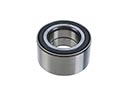 2001 Buick Park Avenue Wheel Bearing
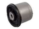 2001 Buick Park Avenue Axle Beam Mount
 2001 Buick Park Avenue Axle Pivot Bushing
 2001 Buick Park Avenue Axle Support Bushings
 2001 Buick Park Avenue Coil Spring Insulator
 2001 Buick Park Avenue Control Arm Bolt
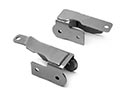 2001 Buick Park Avenue Control Arm Bracket
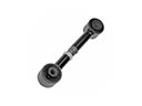 2001 Buick Park Avenue Lateral Link
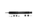 2001 Buick Park Avenue Shock Absorber
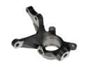 2001 Buick Park Avenue Steering Knuckle
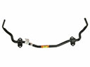 2001 Buick Park Avenue Sway Bar Kit
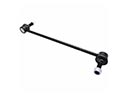 2001 Buick Park Avenue Sway Bar Link