ChevyParts
My Garage
My Account
Cart
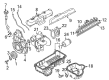
OEM 2001 GMC Savana 2500 Intake Manifold
Engine Intake Manifold- Select Vehicle by Model
- Select Vehicle by VIN
Select Vehicle by Model
orMake
Model
Year
Select Vehicle by VIN
For the most accurate results, select vehicle by your VIN (Vehicle Identification Number).
7 Intake Manifolds found


2001 GMC Savana 2500 Intake Manifold Part Number: 10236744
$60.46 MSRP: $145.77You Save: $85.31 (59%)Product Specifications- Other Name: Manifold, Engine Fuel Intake Manifold
- Item Weight: 5.80 Pounds
- Item Dimensions: 21.8 x 8.9 x 6.4 inches
- Condition: New
- Fitment Type: Direct Replacement
- SKU: 10236744
- Warranty: This genuine part is guaranteed by GM's factory warranty.


2001 GMC Savana 2500 Intake Manifold, Lower Part Number: 17113201
Product Specifications- Other Name: Manifold Kit, Lower Intake; Manifold; Manifold Kit, Engine Fuel Intake Manifold
- Position: Lower
- Item Weight: 29.80 Pounds
- Item Dimensions: 34.3 x 21.4 x 12.6 inches
- Condition: New
- Fitment Type: Direct Replacement
- SKU: 17113201
- Warranty: This genuine part is guaranteed by GM's factory warranty.


2001 GMC Savana 2500 Intake Manifold Part Number: 17113542
Product Specifications- Other Name: Manifold Kit, Engine Fuel Intake Manifold; Manifold
- Position: Upper
- Replaces: 17113213
- Item Weight: 3.30 Pounds
- Item Dimensions: 7.4 x 13.5 x 12.5 inches
- Condition: New
- Fitment Type: Direct Replacement
- SKU: 17113542
- Warranty: This genuine part is guaranteed by GM's factory warranty.


2001 GMC Savana 2500 Intake Manifold Part Number: 17113541
Product Specifications- Other Name: Manifold Kit, Engine Fuel Intake Manifold; Manifold
- Position: Upper
- Item Weight: 4.30 Pounds
- Item Dimensions: 24.0 x 14.8 x 5.2 inches
- Condition: New
- Fitment Type: Direct Replacement
- SKU: 17113541
- Warranty: This genuine part is guaranteed by GM's factory warranty.
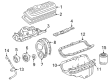
2001 GMC Savana 2500 Intake Manifold, Lower Part Number: 17113342
Product Specifications- Other Name: Manifold Kit, Lower Intake; Manifold; Manifold Kit, Engine Fuel Intake Manifold
- Position: Lower
- Replaces: 17113212
- Item Weight: 23.20 Pounds
- Item Dimensions: 33.4 x 21.4 x 12.4 inches
- Condition: New
- Fitment Type: Direct Replacement
- SKU: 17113342
- Warranty: This genuine part is guaranteed by GM's factory warranty.
2001 GMC Savana 2500 Intake Manifold Part Number: 10236743
Product Specifications- Other Name: Manifold, Engine Fuel Intake Manifold
- Item Weight: 5.10 Pounds
- Item Dimensions: 22.1 x 9.1 x 6.5 inches
- Condition: New
- Fitment Type: Direct Replacement
- SKU: 10236743
- Warranty: This genuine part is guaranteed by GM's factory warranty.

2001 GMC Savana 2500 Intake Manifold Part Number: 10238859
Product Specifications- Other Name: Manifold, Engine Fuel Intake Manifold
- Position: Center
- Item Weight: 3.90 Pounds
- Item Dimensions: 16.8 x 8.7 x 9.0 inches
- Condition: New
- Fitment Type: Direct Replacement
- SKU: 10238859
- Warranty: This genuine part is guaranteed by GM's factory warranty.
2001 GMC Savana 2500 Intake Manifold
With a comprehensive array of OEM 2001 GMC Savana 2500 Intake Manifold, from fuel pumps to door handles, our website is a one-stop-shop for your needs. All our genuine 2001 GMC Savana 2500 Intake Manifold are backed by the manufacturer's warranty and are offered at competitive prices in the market. Rest assured, you can shop with complete confidence.
2001 GMC Savana 2500 Intake Manifold Parts and Q&A
- Q: How to replace the upper intake manifold on 2001 GMC Savana 2500?A: The replacement of an upper Intake Manifold requires starting with the removal of both the engine cover and the pcv tube disconnect from the air cleaner outlet duct. The retaining nut at the air cleaner outlet needs removal before the air cleaner outlet duct can be separated from the Throttle Body assembly. The repair process starts with disconnecting the intake air temperature (IAT) sensor's harness connector and loosening the air cleaner outlet duct before it can detach the duct and the air cleaner assembly from the mass air flow (MAF) sensor. First disconnect the accelerator control cable together with cruise control cable (if present) from both throttle shaft and accelerator control cable bracket. Start by removing the PCV Valve Hose assembly from the Intake Manifold then the valve rocker arm cover before separating the fuel meter body assembly connector and evap canister purge solenoid valve and manifold absolute pressure (MAP) sensor. The installation process begins with removing connections to four key components: the throttle position (TP) sensor, idle air control (IAC) motor and engine coolant temperature (ECT) gauge sensor and a/c high pressure switch (if equipped). Detach the engine wiring harness bracket that is attached to the Intake Manifold stud before moving the harness to a secure position. Next disconnect the a/c vacuum hose while removing the power Brake Booster Vacuum Hose bracket and nut from the Intake Manifold stud. Then disconnect the power Brake Booster Vacuum Hose. Start by removing the accelerator control cable bracket from both the Throttle Body and Intake Manifold before extracting the evap canister purge solenoid and fuel lines from the fuel meter body assembly. The installation process starts with Distributor Cap and Ignition Control Module removal before proceeding to disconnect the upper Intake Manifold studs and remove the manifold. The cleaning process requires separation of the upper Intake Manifold gasket and the fuel meter body assembly's sealing component before excluding assembly of the upper Intake Manifold from cleaning solvent. Wash all joint surfaces and interior areas of the upper Intake Manifold before you check for cracks or loose threads in bolt holes. When performing upper Intake Manifold replacement discard both seals from power brake booster vacuum tube fitting and pcv valve cover before removing Throttle Body and MAP Sensor. Installation begins with Throttle Body and MAP Sensor placement followed by pvc valve cover installation with fresh engine oil-soaked o-ring seal until assembly alignment. Use new lubricated engine oil to seal the power brake booster vacuum tube fitting before locking it into position. After lubricating new components, install the seal on the fuel meter body assembly while placing the upper Intake Manifold to lower Intake Manifold gasket in the groove before securing the upper Intake Manifold onto the lower Intake Manifold. Use threadlock gm p/n 12345382 or equivalent on the upper Intake Manifold bolt threads before installing upper Intake Manifold attaching studs. Apply initial torque at 5 nm (44 inch lbs.) then finish with 9 nm (80 inch lbs.). A complete reinstallation must occur in this order: fuel lines, distributor cap, ignition control module, and evap canister purge solenoid valve. Secure the accelerator control cable bracket and its studs and nuts to the Intake Manifold and Throttle Body while tightening the studs and nuts to 12 nm (106 inch lbs.). Attach the a/c vacuum hose while performing bracket installation and nut tightening for the power Brake Booster Vacuum Hose. Maintain a torque of 11 nm (97 inch lbs.) before power Brake Booster Vacuum Hose connection. Install the engine wiring harness bracket onto the lower Intake Manifold stud before torquing the nut to 12 nm (106 inch lbs.). Follow this process to mate the fuel meter body assembly connector and evap canister purge solenoid valve socket and MAP Sensor connector panels in sequence with the throttle position (TP) sensor and idle air control (IAC) motor and engine coolant temperature (ECT) gauge sensor and a/c high pressure switch (if fitted). Install the PCV Valve Hose assembly between the Intake Manifold and valve rocker arm cover before adding the cruise control cable if present followed by the accelerator control cable. The maf sensor receives the air cleaner outlet duct installation before connecting the iat sensor harness connector and attaching the duct to the Throttle Body assembly while tightening its retaining nut to 2 nm (18 inch lbs.). After connecting the pcv tube into the air cleaner outlet duct you should install both components and finally place the engine cover back in position.
Related 2001 GMC Savana 2500 Parts
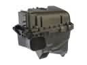 2001 GMC Savana 2500 Air Filter Box
 2001 GMC Savana 2500 Air Hose
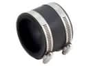 2001 GMC Savana 2500 Air Intake Coupling
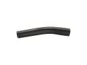 2001 GMC Savana 2500 Fuel Filler Hose
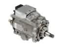 2001 GMC Savana 2500 Fuel Injection Pump
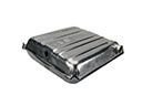 2001 GMC Savana 2500 Fuel Tank
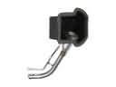 2001 GMC Savana 2500 Fuel Tank Filler Neck
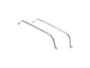 2001 GMC Savana 2500 Fuel Tank Strap
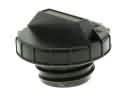 2001 GMC Savana 2500 Gas Cap
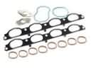 2001 GMC Savana 2500 Intake Manifold Gasket
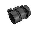 2001 GMC Savana 2500 Mass Air Flow Sensor
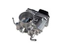 2001 GMC Savana 2500 Throttle Body