ChevyParts
My Garage
My Account
Cart
OEM 2007 Cadillac DTS Coolant Pipe
Engine Cooler Pipe- Select Vehicle by Model
- Select Vehicle by VIN
Select Vehicle by Model
orMake
Model
Year
Select Vehicle by VIN
For the most accurate results, select vehicle by your VIN (Vehicle Identification Number).
2 Coolant Pipes found


2007 Cadillac DTS Overflow Hose Part Number: 21999651
$133.09 MSRP: $198.93You Save: $65.84 (34%)Product Specifications- Other Name: Pipe, Engine Coolant Recovery; Coolant Reservoir Hose; Multi Purpose Hose; Radiator Hose
- Item Weight: 4.40 Pounds
- Item Dimensions: 24.5 x 14.8 x 6.2 inches
- Condition: New
- Fitment Type: Direct Replacement
- SKU: 21999651
- Warranty: This genuine part is guaranteed by GM's factory warranty.


2007 Cadillac DTS Reservoir Hose Part Number: 15773599
$104.61 MSRP: $155.67You Save: $51.06 (33%)Product Specifications- Other Name: Pipe, Engine Coolant Recovery; Coolant Reservoir Hose; Multi Purpose Hose
- Item Weight: 3.60 Pounds
- Item Dimensions: 4.6 x 31.4 x 17.8 inches
- Condition: New
- Fitment Type: Direct Replacement
- SKU: 15773599
- Warranty: This genuine part is guaranteed by GM's factory warranty.
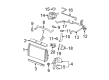
2007 Cadillac DTS Coolant Pipe
With a comprehensive array of OEM 2007 Cadillac DTS Coolant Pipe, from fuel pumps to door handles, our website is a one-stop-shop for your needs. All our genuine 2007 Cadillac DTS Coolant Pipe are backed by the manufacturer's warranty and are offered at competitive prices in the market. Rest assured, you can shop with complete confidence.
2007 Cadillac DTS Coolant Pipe Parts and Q&A
- Q: How to replace the engine crossover coolant pipe on 2007 Cadillac DTS?A: In order to replace the engine coolant crossover pipe, one should start by draining the cooling system and removing an air cleaner, a fuel injector sight shield and the Water Pump Drive Belt. Reposition the Brake Booster Vacuum Hose clamp at the Water Pump housing, and eliminating Brake Booster Vacuum Hose, oil level indicator tube nut, and reposition oil level indicator tube. Next, take off the transaxle vent hose clip from bracket, Throttle Body bolts, bracket, and Throttle Body, discarding the Throttle Body seal. Loosen the Throttle Body dodge duct clamp and remove the Throttle Body dodge duct, remove the fuel rail bracket nut at the rear left lift bracket, reposition the surge tank inlet hose clamp, and remove the surge tank inlet hose. Remove the engine coolant outlet fitting, rear left lift bracket bolt, rear left lift bracket, egr valve shield nuts and shield, egr valve bolts, and EGR Valve, and throw away the EGR Valve Gasket. Remove the engine harness electrical connector from the engine valley electrical connector, raise and support the vehicle, and remove the egr inlet pipe nut from the exhaust manifold front pipe before lowering the vehicle. Replace the bolt holding the egr inlet pipe to the Water Pump housing and get rid of the egr inlet pipe. Then it is necessary to remove the evaporative emission (EVAP) canister purge solenoid valve bolt and solenoid valve, then the manifold absolute pressure (MAP) sensor bracket bolt bracket and MAP Sensor. Reposition the radiator inlet hose clamp using j 38185 hose clamp pliers (J 38185) at the Water Pump housing and remove the radiator inlet hose, reposition the radiator outlet hose clamp at the thermostat housing and remove the radiator outlet hose. Remove the Water Pump belt tensioner studs and tensioner; reposition the heater outlet hose clamp at the heater pipe and remove the heater outlet hose. Drop the Water Pump cover bolt and studs, and loen the Water Pump housing bolts, remove the Water Pump housing with gaskets and bolts. With the Water Pump housing on the bench, remove Water Pump bolts and Water Pump, discarding the Water Pump o-ring. Install a new Water Pump o-ring to the Water Pump then install the Water Pump and tighten it with the bolts to 10 n.m (89 lb in). Mount the Water Pump housing bolts into the designated locations making sure that their specific lengths are used and new Water Pump housing gasket onto the bolts. Set the Water Pump housing to the engine, hand start the bolts and tighten to the level of 25 n.m ( 18 lb ft) in specified order. Mount the Water Pump cover, putting the bolt in lower inboard and studs in the remaining position, tighten Water Pump cover bolt and studs = 10 n.m(89 lb in). Mount the heater outlet hose to the heater pipe mounting the heater outlet hose clamp to the heater pipe. Mount the Water Pump belt tensioner studs and tighten up to 10 n. M (89 lb in). Mount the radiator outlet hose to the thermostat housing, using the j 38185 to locate the radiator outlet hose clamp to the thermostat housing, and then mount the radiator inlet hose to the Water Pump housing and locate the radiator inlet hose clamp to the Water Pump housing. Mount the MAP Sensor and bracket, bracket bolt for 10 n.m (89 lb in), evap canister purge solenoid valve and mounting bolt, tightening to 10-n.m (89 lb in). Hand start the egr inlet pipe nut at the exhaust manifold front pipe, install inlet pipe and bolt into the Water Pump housing, tighten the inlet pipe to 60 n.m (44 lb ft) and bolt to 25 n.m (18 lb ft). Raise and assist the vehicle, tighten the nut on egr inlet pipe to 60 n.m (44 lb ft), lower the vehicle, and plug in engine harness electrical connector to the engine valley electrical connector. Replace the new EGR Valve Gasket, egr valve, and EGR Valve bolts, applying 25 n.m (18 lb ft) torque followed by the EGR Valve shield and shield nuts applying 10 n.m (89 lb in). Align the rear left lift bracket to the Water Pump housing, then bolt the rear left (25 N.m (18 lb ft)) and install the engine coolant outlet fitting to 47 n.m (35 lb ft). Install the surge tank inlet hose to the fitting, position the surge tank inlet hose clamp , and install the fuel rail bracket nut at the rear left lift bracket properly tightening to 10nm (89 lbin). Replace a new Throttle Body plenum duct and tighten the Throttle Body plenum duct clamp to 2.25 n.m (20 lb in). Replace a new Throttle Body seal, Throttle Body, Throttle Body bracket, Throttle Body bolts and tighten to 10 n.m. (89 lb in). Install the transaxle vent hose clip (B), the bracket, the oil level indicator tube, and the oil level indicator tube nut, tightening to 10 n.m (89 lb-in). Mount the Brake Booster Vacuum Hose to the Water Pump housing attaching the brake booster hose clamp at Water Pump housing mount the Water Pump Drive Belt air cleaner, fill the cooling system, install the fuel injector sight shield.
Related 2007 Cadillac DTS Parts
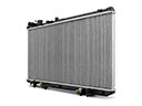 2007 Cadillac DTS Radiator
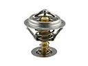 2007 Cadillac DTS Thermostat
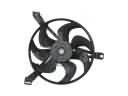 2007 Cadillac DTS A/C Condenser Fan
 2007 Cadillac DTS Belt Tensioner Bolt
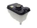 2007 Cadillac DTS Coolant Reservoir
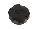 2007 Cadillac DTS Coolant Reservoir Cap
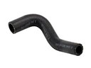 2007 Cadillac DTS Cooling Hose
 2007 Cadillac DTS Fan Motor
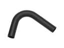 2007 Cadillac DTS Radiator Hose
 2007 Cadillac DTS Thermostat Gasket
 2007 Cadillac DTS Thermostat Housing
 2007 Cadillac DTS Water Pump Gasket