
Popular OEM Cadillac DTS Parts
- Body & Hardware Parts View More >
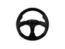
- Steering Parts View More >
- Electrical Parts View More >
- Air & Fuel Delivery Parts View More >
- Charging & Starting Parts View More >
- Engine Parts View More >
- Belts & Cooling Parts View More >
- Suspension Parts View More >
- Emission Control & Exhaust Parts View More >
- Transmission Parts View More >
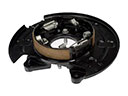
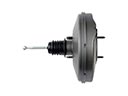
- Brakes Parts View More >
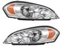
- Headlights & Lighting Parts View More >


Why Buy Genuine Cadillac DTS Parts From ChevyPartsGiant.com
Looking for real Cadillac DTS parts? ChevyPartsGiant.com may be a better choice to find genuine parts at wallet-friendly prices. We sell only OEM Cadillac DTS parts, ensuring perfect fit, reliability, and long-term performance. With our website, you can easily get access to the same parts found at local Cadillac stores. All components are produced by Cadillac and are exclusively fitted on Cadillac DTS automobiles. By shopping at our store, you can enjoy the quality of the Cadillac factory without the high prices of brick-and-mortar facilities. We achieve this because we are an online store operating at lower costs, which we pass on to you. We also have a user-friendly platform where you can find and order genuine Cadillac DTS parts swiftly. We are here to make your process of restoring a Cadillac DTS or dealing with simple repairs quick and inexpensive. We also make it easy to obtain Cadillac DTS parts at competitive shipping prices and a team of knowledgeable staff ready to take your order. Choose ChevyPartsGiant.com to save time and money, as well as keep your Cadillac DTS in the good condition.
The Cadillac DTS made its debut at the 2005 Chicago Auto Show then achieved market success from 2006 until 2011. The luxury sedan powered by the 4.6L Northstar V8 engine produces its maximum power output from 275 hp to 291 hp depending on which trim version customers select. Such an installation enhances the Cadillac DTS's performance characteristics while providing its users with superior ride refinement. The Cadillac DTS used a 4T80-E 4-speed automatic transmission which delivered smooth power transfers although it lacked multi-speed technology that competitors had implemented. Professional motor technicians at Cadillac designed the DTS with safety features including electronic stability control plus antilock disc brakes as well as multiple airbags to merge safe driving with comfortable experiences for users. Spacious interior design in the Cadillac DTS is enhanced by power-adjustable seats together with controls that make the driving experience convenient for everyone. The Cadillac DTS received Presidential State Car status through its presentation of combined superior safety components with premium amenities. The Cadillac DTS needs original replacement parts to preserve reliability due to their precise factory standards which give proper fitment and durable operational capability. The brand stays committed to delivering exceptional high-end parts for Cadillac DTS automobiles to showcase their premium sedan capabilities along with luxury characteristics.
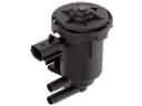
Cadillac DTS divides three problems into three groups: fuel delivery, ignition, and brakes, electronics to facilitate in diagnosing the system. The Cadillac DTS may have its power delivery stall or crank without starting. A weak pump on fuel connections develops less pressure when hot and with a heavy load. Lower the rail pressure, check the power and ground, and replace the fuel pump and filter. Put the fuses on the tank harnesses and relay to prevent a voltage loss. To start the engine, the DTS can misfire with flickering light and jerky idling. One ignition coil on a bank deteriorates with age and heat and causes a spark drop. Change the plugs when necessary, and the ignition coil assembly that has gone bad. Check intake leakage with a smoke test and adjust calibrations where necessary. In a brake control, the Cadillac DTS may light up the ABS lamp and diminish damping. The internal malfunctions in the ABS control module interfere with processing the wheel speed and pump commands. Clear grounds and powers, transplant the ABS control module, and finish. Check on wheel speed signals and tone rings prior to module condemnation. Repairs done to the DTS must make it take off fast, idle openly, and shut off with the exact pedal feel of the pedal. The Cadillac DTS cost of ownership is dominated by the factory recommended scheduled preventive service charges, the costs prevented by actual schedules, and the scheduled preventative maintenance costs.
Cadillac DTS Parts Questions & Answers
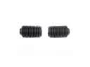
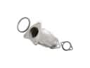
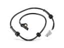
- Q: How to Change a Snap-In Style TPMS Sensor on Cadillac DTS?A:To replace the Tire Pressure Indicator Sensor (Snap In Style), lift up the vehicle on a suitable support, first. First, pull the vehicle lug nuts with the car jack to raise the vehicle, loosen the lug nuts, and finish removing the nuts afterward. Alway replace the damaged prong with a new one type of SCHADDER(R) tire pressure monitor and use a new TORX screw. Pull out the driver-like TORX screw located on the tire pressure sensor and pull it straight off from the tire pressure valve stem carefully without scratching or damaging the clear aluminum on the wheels. Afterward, pull the tire pressure valve stem out of the rim. When installing, make sure the flat of valve lines up with the flats of snap in enclosure do not forget that TPM valves and TORX screws are one time use. Mount the tire pressure sensor to the valve stem and replace the new TORX screw, screwing it down to 1.3 N.m (11.5 lb in). Use a government-approved tire mounting lubricant while not using silicon or corrosion base compounds. Check the valve is functioning properly, press the valve stem so that it moves parallel to hole of rim paste the rubber piece with tire soap let it dry for supper. Please note that Snap Fit TPM sensors were on the OFF state when they were shipped, but will leave this state as soon as the tire is inflated, so they can program the vehicle as they normally did. Lastly, mount the tire to rim and install the tire/wheel assembly to the vehicle, bring up the vehicle, learn how to read the tire pressure sensors.
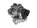
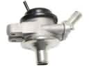
- Q: How should you inspect the Power Steering Pump for leaks and what should you do if it needs replacement on Cadillac DTS?A:avoide inspection of the hydraulic pump for leaks and refrain from dismantling the hydraulic pump. In cases where replacement of the pump is necessary the user should first remove the reservoir assembly.
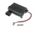
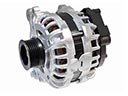
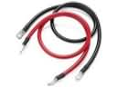
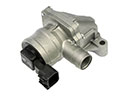
- Q: How to replace the alternator on Cadillac DTS?A:For changing the generator, turn off the negative Battery Cable, remove the Radiator and the Drive Belt. Disconnect the engine wiring harness electric connector from the generator, move the starter solenoid cable protective boot from the generator, remove generator terminal nut, after which the starter solenoid cable terminal is removed. Next, unbolt the generator and move the cable out of the way (engine ground cable) before pulling out the generator. For the installation, place the generator to the engine and install the generator bolts finger tight in the manner. Upper bolt, side bolt, and lower bolt, tightening them up to 50 nm (37 ft. Lbs.). Replace starter solenoid cable terminal and fix generator terminal nut to 12 nm (106 inch lbs.). Move the starter solenoid cable protective boot to the generator and connect the engine wiring harness electrical connector to the generator and then install a Drive Belt and radiators before reconnecting the negative Battery Cable.
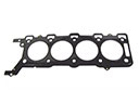
- Q: How to replace the left camshaft on Cadillac DTS?A:The replacement procedure for the left Camshaft starts with removing the left Camshaft cover while moving the Crankshaft to tdc of compression stroke for #1 cylinder. Both Camshaft sprocket drive pins must be positioned at their highest point of rotation. Using the Camshaft holding tool (J 44212) install it over the camshafts while noting the nearby chain link positions using a paint stick. After installing the Timing Chain retention tool (EN 46327) you should rotate the wing nut (EN 46327) to its highest position. Then position the bottom retention tool on the Cylinder Head near the left exhaust Camshaft sprocket and chain followed by hooking the hook end into a secondary Timing Chain link. Procedure for locking the chain begins with positioning the bottom retention tool near to the left intake Camshaft sprocket and chain. At this point you should not tighten the wing nut. The same steps should then be performed on the upper retention tool located next to the left exhaust Camshaft sprocket and chain. Finish the chain retention process by alternate tighte make use of an open wrench on the hex cast of the camshafts to stop their rotation during the removal of the sprocket bolts and sprockets. Before removing the camshafts with Camshaft followers you need to loosen the bearing cap bolts alternating between each one until valve spring pressure is gone and then remove the bearing caps along with the Camshaft holding tool (J 44212). Carefully examine the camshafts afterward cleaning them while applying lubrication to both the roller pivot pocket on followers and valve slot before mounting them accurately to the valve tip and stationary hydraulic lash adjusters (SHLA). First clean the carriers then apply lubrication to all parts including the Camshaft carriers while placing the Camshaft into the carriers with sprocket drive pins positioned close to the top rotational position. The Camshaft bearing caps need installation following the observation of their markings before applying lubrication to them. Perform bearing cap installation based on these identification marks. The angle meter (J 45059) helps users tighten the Camshaft bearing cap bolts to 5 n.m (44 lb in) while completing another 30 degrees of rotation. The camshafts need alignment followed by Camshaft holding tool (J 44212) reinstallation to install intake and exhaust Camshaft sprockets according to paint marks used during the dismantling process. The open wrench should be used to restrain rotation of the Camshaft sprocket bolts until they reach 120 n.m (89 lb ft) torque. After this, extract the Timing Chain retention tool (EN 46327) and inspect Camshaft sprocket alignment. Finally, remove the Camshaft holding tool (J 44212) for left Camshaft cover installation.


