ChevyParts
My Garage
My Account
Cart
OEM Cadillac DTS Coolant Pipe
Engine Cooler Pipe- Select Vehicle by Model
- Select Vehicle by VIN
Select Vehicle by Model
orMake
Model
Year
Select Vehicle by VIN
For the most accurate results, select vehicle by your VIN (Vehicle Identification Number).
2 Coolant Pipes found


Cadillac DTS Overflow Hose Part Number: 21999651
$133.09 MSRP: $198.93You Save: $65.84 (34%)


Cadillac DTS Reservoir Hose Part Number: 15773599
$104.61 MSRP: $155.67You Save: $51.06 (33%)
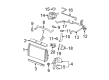
Cadillac DTS Coolant Pipe
Want to cut long-term maintenance and repair costs? Choose OEM Coolant Pipe. Those parts deliver top durability you can trust. On our site, you'll find a huge catalog of genuine Cadillac DTS parts. Prices are unbeatable, so you can keep more in your pocket. Every OEM Cadillac DTS Coolant Pipe includes a manufacturer's warranty. You can also get an easy return policy that keeps buying risk free. Fast delivery, get your car on the road quickly. It's simple to search, compare, and order. Stop guessing about quality or fit. Order today and save with parts that last.
Cadillac DTS Coolant Pipe Parts Questions & Experts Answers
- Q: How to replace the crossover coolant pipe on Cadillac DTS?A:The coolant crossover pipe replacement procedure requires draining the cooling system and removing both the air cleaner and fuel injector sight shield and Water Pump Drive Belt. Move the Brake Booster Vacuum Hose clamp at the Water Pump housing then take out the Brake Booster Vacuum Hose. When replacing the oil level indicator tube remove its nut then move the tube to its final position. Begin by detaching the transaxle vent hose clip from its bracket, proceeding to disconnect the Throttle Body bolts, bracket and Throttle Body, garbage the Throttle Body seal. Remove the Throttle Body plenum duct after you loosen its clamp for disposal. Climb to the rear left lift bracket and remove its fuel rail bracket nut before repositioning the surge tank inlet hose clamp to detach the inlet hose. First you need to remove three main components: the engine coolant outlet fitting and the rear left lift bracket bolt then the bracket. Begin by taking off shield nuts from the EGR Valve then removing the shield before safely disposing of the valve along with its gasket. Using the j38185 hose clamp pliers (J38185) remove the egr inlet pipe bolt from the Water Pump housing while making sure to replace the inlet pipe if disconnected. Disconnect the engine harness electrical connector from the engine valley electrical connector. First separate the egr inlet pipe from its housing and remove the evap canister purge solenoid valve bolt before moving onto the valve. The bolt locking the MAP Sensor bracket allows removal together with the bracket itself and the sensor device. J38185 hose clamp pliers (J38185) help users shift the radiator inlet hose clamp near the Water Pump housing before removing the inlet hose. Replace the housing clamp supporting the outlet radiator line at the Thermostat Housing before extracting the outlet hose. The heater outlet hose should have its clamp repositioned to the heater pipe before removing the outlet hose. Following the removal of Water Pump cover bolt and studs, the cover needs to be taken out after loosening and removing the Water Pump housing together with its gaskets and bolts. The bench procedure requires housing removal to detach Water Pump bolts followed by discarding the o-ring. Place the new Water Pump o-ring onto the pump before installation while torquing the bolts to 10 nm (89 inch lbs.). The Water Pump housing requires installation of its bolts according to specified length measurements: first, bolt 40.7 mm, bolts 92.0 mm, bolts 109.0 mm, and bolts 115.0 mm. Install a new Water Pump housing gasket after tightening the following bolts: bolt 40.7 mm, bolts 92.0 mm, bolts 109.0 mm, and bolts 115.0 mm. Position the housing to its engine location then begin hand torquing the bolts to a 25 nm (18 ft. Lbs.) final torque value in the precise sequence. Screw the Water Pump cover's bolt into the lower inboard space first and place the studs into remaining locations before final tightening at 10 nm (89 inch lbs.). Using the heater pipe thread the hose back into place and secure the clamp properly. Set the Water Pump belt tensioner into position before installing its attachments which require 10 nm (89 inch lbs.) torques. Use the j38185 tool to position radiator outlet hose clamps at the Thermostat Housing before attaching radiator inlet hose clamps between Water Pump housing. Compare these components to their original torque specifications before tightening all components to 10 nm (89 inch lbs.). You should replace the evap canister purge solenoid valve with its bolt to a torque specification of 10 nm (89 inch lbs.). Begin installation of the new egr inlet pipe nut at the exhaust manifold front pipe before implementing the inlet pipe and bolt connection to the Water Pump housing. Torque both components to 60 nm (44 ft. Lbs.) and 25 nm (18 ft. Lbs.), respectively. The electrical engine harness should be connected first before installing the new EGR Valve Gasket followed by EGR Valve and securing both bolts at 25 nm (18 ft. Lbs.). Fasten the EGR Valve shield while tightening the nuts to 10 nm (89 inch lbs.). Secure the rear left lift bracket to the Water Pump housing followed by installing and tightening the bolt to 25 nm (18 ft. Lbs.). First install the engine coolant outlet fitting while tightening it to 47 nm (35 ft. Lbs.). Install next the surge tank inlet hose followed by its clamp. Drive the fuel rail bracket nut at the rear left lift bracket with a torque of 10 nm (89 inch lbs.). Use no sealant when securing the Water Pump housing to the plenum then fit a modern Throttle Body plenum duct while setting the clamp to 2.25 nm torque (20 inch lbs.). Install a new Throttle Body seal along with the Throttle Body and bracket hardware and tighten all bolts to 10 nm (89 inch lbs.). Familiarize the transaxle vent hose clip to its bracket while obtaining proper tube alignment then fasten the nut with 10 nm (89 inch lbs.) torque. Put back the Brake Booster Vacuum Hose with clamp onto the Water Pump housing before setting the Water Pump Drive Belt followed by air cleaner assembly and cool system filling then fuel injector sight shield installation.

Related Cadillac DTS Parts
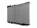 Cadillac DTS Radiator
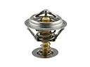 Cadillac DTS Thermostat
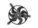 Cadillac DTS A/C Condenser Fan
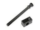 Cadillac DTS Belt Tensioner Bolt
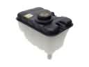 Cadillac DTS Coolant Reservoir
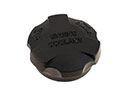 Cadillac DTS Coolant Reservoir Cap
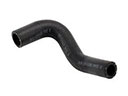 Cadillac DTS Cooling Hose
 Cadillac DTS Fan Motor
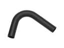 Cadillac DTS Radiator Hose
 Cadillac DTS Thermostat Gasket
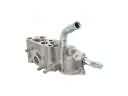 Cadillac DTS Thermostat Housing
 Cadillac DTS Water Pump Gasket