ChevyParts
My Garage
My Account
Cart
OEM Cadillac Catera Front Cross-Member
Front Engine Cross Member- Select Vehicle by Model
- Select Vehicle by VIN
Select Vehicle by Model
orMake
Model
Year
Select Vehicle by VIN
For the most accurate results, select vehicle by your VIN (Vehicle Identification Number).
1 Front Cross-Member found

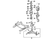
Cadillac Catera Engine Cradle Part Number: 9127270
Cadillac Catera Front Cross-Member
Want to cut long-term maintenance and repair costs? Choose OEM Front Cross-Member. Those parts deliver top durability you can trust. On our site, you'll find a huge catalog of genuine Cadillac Catera parts. Prices are unbeatable, so you can keep more in your pocket. Every OEM Cadillac Catera Front Cross-Member includes a manufacturer's warranty. You can also get an easy return policy that keeps buying risk free. Fast delivery, get your car on the road quickly. It's simple to search, compare, and order. Stop guessing about quality or fit. Order today and save with parts that last.
Cadillac Catera Front Cross-Member Parts and Q&A
- Q: How to replace the Front Cross-Member on Cadillac Catera?A:To replace the front suspension cross member, start by attaching the engine support fixture (J28467-A) at the lift points and lifting the vehicle without dropping it on the ground. Ensure that the vehicle tipping is firmly held. Univolt the front wheel assemblies, Wheel Speed Sensors, brake wear indicator wires, brake flex hose clips, and hoses off the strut assemblies. Remove the brake caliper assembly bolts from the Steering Knuckles and support the caliper assemblies in order to avoid damaging them. Then, take out the outer tie rod nuts and use the tie rod/wheel stud puller (J6627-A) in order to pull the outer tie rod ball studs away from the steering knuckles. Remove the pinch bolts on the lower control arm ball stud and the steering knuckles from the lower control arm ball studs, remove the stabilizer shaft link nuts and the links as well. Subsequently, unbolt the engine mount and support the crossmember frame and then unbolt the engine front crossmember frame bolts and lower the frame. For installation, place the front crossmember frame and use new engine front crossmember frame bolts and tighten them such that use of torque/angle meter (J36660-A) value of set torque is achieved. Install the engine mount nuts, stabilizer shaft links, and their nuts adjusting them appropriately. Reattach steering knuckles to the lower control arm ball studs using new pinch bolts and attach the outer tie rods using the linkage installer (J42089) to tighten the tie rod ball studs. Apply new self-locking outer tie rod nuts, and check that the brake caliper assembly is cleaned and coated with locking compound at the time of reassembling the caliper assemblies with the torque/angle meter (J36660-A). Lastly, reconnect the wiring for Wheel Speed Sensor and brake wear indicator wires, brake hoses, and wheel speed sensors, tighten the Wheel Speed Sensor bolts, reinstall the front wheeal assemblies, lower the vehicle, and align the wheels.
Related Cadillac Catera Parts
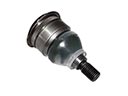 Cadillac Catera Ball Joint
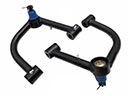 Cadillac Catera Control Arm
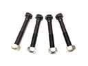 Cadillac Catera Control Arm Bolt
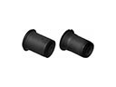 Cadillac Catera Control Arm Bushing
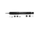 Cadillac Catera Shock Absorber
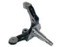 Cadillac Catera Spindle
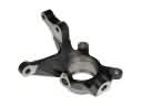 Cadillac Catera Steering Knuckle
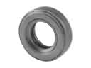 Cadillac Catera Strut Bearing
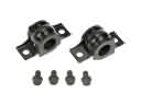 Cadillac Catera Sway Bar Bracket
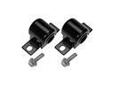 Cadillac Catera Sway Bar Bushing
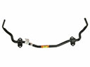 Cadillac Catera Sway Bar Kit
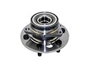 Cadillac Catera Wheel Hub