ChevyParts
My Garage
My Account
Cart
OEM Chevrolet Camaro A/C Switch
Air Conditioning Switch- Select Vehicle by Model
- Select Vehicle by VIN
Select Vehicle by Model
orMake
Model
Year
Select Vehicle by VIN
For the most accurate results, select vehicle by your VIN (Vehicle Identification Number).
26 A/C Switches found

Chevrolet Camaro Control Module Part Number: 84583887
$82.23 MSRP: $168.98You Save: $86.75 (52%)Ships in 1-2 Business Days
Chevrolet Camaro Control Module Part Number: 84583886
$82.23 MSRP: $168.98You Save: $86.75 (52%)Ships in 1-2 Business DaysChevrolet Camaro Control Module Part Number: 84518386
$82.23 MSRP: $168.98You Save: $86.75 (52%)Ships in 1-2 Business Days


Chevrolet Camaro Control Panel Part Number: 20990311
$398.55 MSRP: $595.73You Save: $197.18 (34%)

Chevrolet Camaro Blower Motor Switch Part Number: 16015450

Chevrolet Camaro Temperature Control Part Number: 16183811

Chevrolet Camaro Temperature Control Part Number: 9351461
Chevrolet Camaro Dash Control Unit Part Number: 16069782

Chevrolet Camaro Blower Motor Switch Part Number: 16039106

Chevrolet Camaro Blower Motor Switch Part Number: 16159876

Chevrolet Camaro Dash Control Unit Part Number: 16066061
Chevrolet Camaro Temperature Control Part Number: 16183801
Chevrolet Camaro Temperature Control Part Number: 16190411

Chevrolet Camaro Dash Control Unit Part Number: 1226879
Chevrolet Camaro Temperature Control Part Number: 16190421
Chevrolet Camaro Temperature Control Part Number: 16216461

Chevrolet Camaro Dash Control Unit Part Number: 16089441
Chevrolet Camaro Dash Control Unit Part Number: 16089611
Chevrolet Camaro Trim Plate Part Number: 16066071
Chevrolet Camaro Temperature Control Part Number: 16216451
| Page 1 of 2 |Next >
1-20 of 26 Results
Chevrolet Camaro A/C Switch
Want to cut long-term maintenance and repair costs? Choose OEM A/C Switch. Those parts deliver top durability you can trust. On our site, you'll find a huge catalog of genuine Chevrolet Camaro parts. Prices are unbeatable, so you can keep more in your pocket. Every OEM Chevrolet Camaro A/C Switch includes a manufacturer's warranty. You can also get an easy return policy that keeps buying risk free. Fast delivery, get your car on the road quickly. It's simple to search, compare, and order. Stop guessing about quality or fit. Order today and save with parts that last.
Chevrolet Camaro A/C Switch Parts Questions & Experts Answers
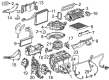
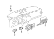
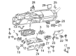
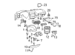
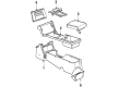
- Q: How to replace the A/C Switch control assembly on Chevrolet Camaro?A:Begin A/C Switch replacement by removing the accessory trim plate and the screws attaching the A/C Switch. The A/C Switch must be extracted from the instrument panel to access vacuum and electrical and temperature cable connections. The vacuum harness connector requires removal alongside several electrical connectors which include a/c mode switch and a/c control illumination and a/c blower switch and rear defogger. Four components include a/c mode switch, a/c control illumination, a/c blower switch, and rear defogger. To take off the temperature control cable from the A/C Switch, users should employ a small screwdriver to unclip the control cable connectors. Begin installation by attaching the temperature control cable connector to the A/C Switch and then proceeding with connecting the electrical connectors: rear defogger, a/c blower switch, a/c control illumination, and a/c mode switch. The system consists of rear defogger and a/c blower switch and a/c control illumination as well as a/c mode switch. The A/C Switch requires installation along with connection of the vacuum harness connector. Tighten all screws to 2.2 n.m (19 lb in) according to fastener notice specifications. You need to reinstall the accessory trim plate as the last step.

Related Chevrolet Camaro Parts
 Chevrolet Camaro A/C Compressor
 Chevrolet Camaro A/C Condenser
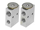 Chevrolet Camaro A/C Expansion Valve
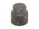 Chevrolet Camaro A/C Service Cap
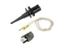 Chevrolet Camaro Air Temperature Sensor
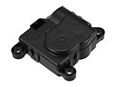 Chevrolet Camaro Blend Door Actuator
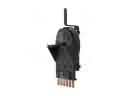 Chevrolet Camaro Blower Control Switches
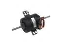 Chevrolet Camaro Blower Motor
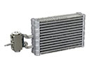 Chevrolet Camaro Evaporator
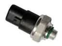 Chevrolet Camaro HVAC Pressure Switch
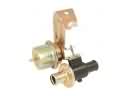 Chevrolet Camaro Heater Control Valve
 Chevrolet Camaro Heater Core