ChevyParts
My Garage
My Account
Cart
OEM Chevrolet Classic Fan Shroud
Radiator Fan Shroud- Select Vehicle by Model
- Select Vehicle by VIN
Select Vehicle by Model
orMake
Model
Year
Select Vehicle by VIN
For the most accurate results, select vehicle by your VIN (Vehicle Identification Number).
1 Fan Shroud found

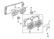
Chevrolet Classic Fan Shroud Part Number: 88957397
Chevrolet Classic Fan Shroud
Want to cut long-term maintenance and repair costs? Choose OEM Fan Shroud. Those parts deliver top durability you can trust. On our site, you'll find a huge catalog of genuine Chevrolet Classic parts. Prices are unbeatable, so you can keep more in your pocket. Every OEM Chevrolet Classic Fan Shroud includes a manufacturer's warranty. You can also get an easy return policy that keeps buying risk free. Fast delivery, get your car on the road quickly. It's simple to search, compare, and order. Stop guessing about quality or fit. Order today and save with parts that last.
Chevrolet Classic Fan Shroud Parts Questions & Experts Answers
- Q: How to replace the fan shroud on Chevrolet Classic?A:You must begin the Fan Shroud replacement by removing the battery and accessing the battery tray. Recovery of the air conditioning system along with draining the cooling system must also occur. The j 38185 hose clamp pliers (J 38185) provides assistance to move the Radiator inlet hose clamp to position while extracting the Radiator inlet hose off the Radiator. Refit the j 38185 hose clamp pliers to shift the surge tank outlet/radiator outlet hose clamp position followed by disconnecting the surge tank outlet/radiator outlet hose from the surge tank and then proceeding to the Radiator vent hose and upper transaxle cooler line. The refrigerant pressure sensor electrical connector disconnectes while a condenser inlet fits off the discharge hose through capping or taping of the open A/C Hose to prevent contamination. Use the j 38185 to disconnect the cooling fan electrical connectors and then remove the surge tank outlet/radiator outlet hose bolt attached to the Intake Manifold. To begin the procedure raise the vehicle and discard the lower closeout panel. The j 38185 tool will aid in repositioning the surge tank outlet/radiator outlet hose clamp before extraction of the surge tank outlet/radiator outlet hose from the Radiator while the lower transaxle cooler line and evaporator hose to condenser bolt are also removed. Disconnect the evaporator hose from the condenser while discarding its sealing washer before taking off the lower Radiator support mounting panel together with the Radiator and fan and condenser assembly from the vehicle. Begin the process of Radiator removal by taking off the Fan Shroud along with fan nuts that secure the fans (1,8), afterward remove the fans (1,8) from their Fan Motors (7,3). The cooling Fan Motor bolts (3,7) and bolts (5,6) from the cooling fan brackets enable removal of the cooling fan brackets (5,6) from the Fan Shroud. You should install the cooling fan brackets (5,6) onto the Fan Shroud before securing them with Cooling Fan Bracket bolts that need a torque of 10 nm (89 inch lbs.). Secure the fans (1,8) to the fan motors (7,3) by tightening fannuts to 6 nm (53 inch lbs.) and install cooling Fan Motor bolts on cooling fan motors (3,7) to a torque of 6 nm (53 inch lbs.). Reinstall the Radiator as well as the fan with condenser assembly to the vehicle before tightening the lower Radiator support mounting panel to 10 nm (89 inch lbs.). The service technician should first remove tape or cap from the evaporator hose and apply a new sealing washer on the condenser end before connecting the evaporator hose to the condenser outlet and securing its outlet bolt with 25 nm (18 ft. Lbs.) of torque. The final step includes installing the lower transaxle cooler line at 30 nm (22 ft. Lbs.) and the surge tank outlet/radiator outlet hose to the Radiator while using the j 38185 tool to position the surge tank outlet/radiator outlet hose clamp. Lower the vehicle while reinstalling the lower closeout panel and connecting the electro-mechanical cooling fan electrical interface. After tightening the Intake Manifold bolt for the surge tank outlet/radiator outlet hose the technician should remove discharge hose tape or cap while installing a fresh sealing washer to finish by connecting and tightening the discharge hose to the condenser inlet fitting to 25 nm (18 ft. Lbs.). The technician reconnects the refrigerant pressure sensor electrical connector as well as the upper transaxle oil cooler line and torques them to 30 nm (22 ft. Lbs.). Then they install the Radiator vent hose and the surge tank outlet Radiator outlet hose and position the surge tank outlet/radiator outlet hose clamp using the j 38185 tool. The Radiator inlet hose gets installed on the Radiator while utilizing the j 38185 to position the Radiator inlet hose clamp correctly before refilling the cooling system and performing recharging of the a/c system following a halogen leak test of the reconstructed components with the j 39400-a halogen leak detector (J 39400-A). The process should end with battery tray and battery installation.

Related Chevrolet Classic Parts
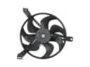 Chevrolet Classic A/C Condenser Fan
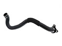 Chevrolet Classic Coolant Pipe
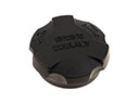 Chevrolet Classic Coolant Reservoir Cap
 Chevrolet Classic Daytime Running Light Relay
 Chevrolet Classic Fuel Pump Relay
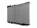 Chevrolet Classic Radiator
 Chevrolet Classic Radiator Cap
 Chevrolet Classic Radiator Hose
 Chevrolet Classic Radiator fan
 Chevrolet Classic Thermostat Housing
 Chevrolet Classic Variable Timing Sprocket
 Chevrolet Classic Water Pump