ChevyParts
My Garage
My Account
Cart
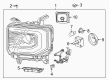
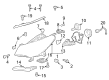
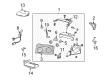
OEM Chevrolet Light Control Module
- Select Vehicle by Model
- Select Vehicle by VIN
Select Vehicle by Model
orMake
Model
Year
Select Vehicle by VIN
For the most accurate results, select vehicle by your VIN (Vehicle Identification Number).
27 Light Control Modules found


Chevrolet Control Module Part Number: 23507118
$129.16 MSRP: $184.82You Save: $55.66 (31%)Ships in 1-2 Business DaysProduct Specifications- Other Name: Module, Headlamp/Fog Lamp/Turn Signal; Lighting Control Module; Module
- Replaces: 23219988


Chevrolet Control Module Part Number: 22853757
$267.78 MSRP: $389.86You Save: $122.08 (32%)Product Specifications- Other Name: Module, Headlamp/Fog Lamp/Turn Signal; Lighting Control Module; Hid Bulb Ballast; Bulb Ballast; Ballast; Module
- Replaces: 22869158

Chevrolet Control Module Part Number: 13541369
$67.93 MSRP: $101.10You Save: $33.17 (33%)Ships in 1-3 Business DaysProduct Specifications- Other Name: Module Assembly-Exterior Lighting Control; Lighting Control Module
- Replaced by: 13547246

Chevrolet Control Module Part Number: 84893099
$50.08 MSRP: $102.92You Save: $52.84 (52%)Ships in 1-2 Business DaysProduct Specifications- Other Name: Module Assembly, Headlamp Led Driver; Lighting Control Module; Module; Module, Headlamp/Fog Lamp/Turn Signal
- Replaces: 23244889, 84292726

Chevrolet Control Module Part Number: 16523917
$390.11 MSRP: $583.23You Save: $193.12 (34%)Product Specifications- Other Name: Module, Concealed Capsule/Headlamp Control; Lighting Control Module; Actuator Relay; Module
- Replaces: 16521297, 16505400

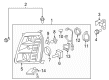
Chevrolet Control Module, Driver Side Part Number: 84547823
$123.95 MSRP: $185.32You Save: $61.37 (34%)Ships in 1-3 Business DaysProduct Specifications- Other Name: Module Assembly-Headlamp Led Driver; Lighting Control Module; Module; Module, Headlamp/Fog Lamp/Turn Signal
- Position: Driver Side

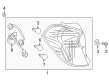
Chevrolet Socket & Wire Part Number: 94543743
$35.71 MSRP: $53.14You Save: $17.43 (33%)Ships in 1-3 Business DaysProduct Specifications- Other Name: Module, Tail Lamp
- Position: Rear


Chevrolet Control Module Part Number: 25883862
$153.09 MSRP: $228.88You Save: $75.79 (34%)Product Specifications- Other Name: Module, Headlamp/Fog Lamp/Turn Signal; Lighting Control Module; Module


Chevrolet Control Module Part Number: 12135174
Product Specifications- Other Name: Module, Headlamp/Fog Lamp/Turn Signal; Module
- Replaces: 12135124


Chevrolet Control Module Part Number: 10304215
Product Specifications- Other Name: Module, Headlamp/Fog Lamp/Turn Signal


Chevrolet Control Module Part Number: 10407669
Product Specifications- Other Name: Module, Headlamp/Fog Lamp/Turn Signal; Daytime Running Light Module; Sentinel Module; Module
- Replaces: 10261144

Chevrolet Control Module Part Number: 30020891
Product Specifications- Other Name: Module, Headlamp/Fog Lamp/Turn Signal; Daytime Running Light Module

Chevrolet Control Module Part Number: 10098680
Product Specifications- Other Name: Module, Headlamp/Fog Lamp/Turn Signal; Module

Chevrolet Daytime Running Light Module Part Number: 12088547
Product Specifications- Other Name: Module, Headlamp/Fog Lamp/Turn Signal; Module

Chevrolet Module Part Number: 10220653
Product Specifications- Other Name: Module, Headlamp/Fog Lamp/Turn Signal

Chevrolet Daytime Running Light Module Part Number: 30019168
Product Specifications- Other Name: Module, Headlamp/Fog Lamp/Turn Signal; Module
Chevrolet Control Module Part Number: 30025475
Product Specifications- Other Name: Module, Headlamp/Fog Lamp/Turn Signal; Daytime Running Light Module

Chevrolet Module Part Number: 10076724
Product Specifications- Other Name: Module Assembly-Headlamp Auto Control; Lighting Control Module; Module, Headlamp/Fog Lamp/Turn Signal

Chevrolet Module Part Number: 12088534
Product Specifications- Other Name: Module, Headlamp/Fog Lamp/Turn Signal
Chevrolet Module Part Number: 12182135
Product Specifications- Other Name: Module, Headlamp/Fog Lamp/Turn Signal
| Page 1 of 2 |Next >
1-20 of 27 Results
Chevrolet Light Control Module
Want to cut long-term maintenance and repair costs? Choose OEM Light Control Module. Those parts deliver top durability you can trust. On our site, you'll find a huge catalog of genuine Chevrolet parts. Prices are unbeatable, so you can keep more in your pocket. Every OEM Chevrolet Light Control Module includes a manufacturer's warranty. You can also get an easy return policy that keeps buying risk free. Fast delivery, get your car on the road quickly. It's simple to search, compare, and order. Stop guessing about quality or fit. Order today and save with parts that last.
Chevrolet Light Control Module Parts Questions & Experts Answers
- Q: How to service and repair the Light Control Module on Chevrolet Aveo?A:The first step to replace the lamp control module involves disconnecting the negative Battery Cable. Start by removing the instrument panel low cover while also unscrewing the lamp control module before disconnecting its electrical connector. During installation the lamp control module needs screws to secure it alongside reconnection of the electrical connector. Install the instrument panel low cover and reconnect the negative Battery Cable after completing the installation.
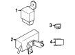
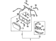
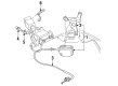
- Q: How to replace the Front Light Control Module on Chevrolet Corvette?A:The first step to replace the headlamp control module requires removal of the passenger side front floor kick up panel cover for access to the instrument panel (IP) electrical center followed by extracting the headlamp circuit breaker from the center. Head to the hood to operate the rh headlamp manually by turning the headlamp motor/actuator manual control knob towards the opposite direction. This will help you lift the headlamp into position. First disconnect the wiring harness electrical connector from the forward lamp wiring harness and then raise your vehicle while supporting it safely. The first task involves taking off the front fascia lower closeout panel followed by detaching the brake caliper cooling duct from the front fascia before setting it aside. The first step requires disconnecting power connectors from the headlamp control module before removing its mounting nuts for bracket removal. The new headlamp control module requires mounting on the headlamp bracket followed by fastening it with mounting nuts. The electrical connectors need reattachment to the module before reinstalling the brake caliper cooling duct into its position on the front fascia and applying force to secure it. After installing the front fascia lower panel attach the vehicle to the ground while reconnecting the headlamp wiring harness of the right side to the forward lamp wiring harness. To manually lower the rh headlamp users should turn the headlamp motor/actuator manual control knob to the clockwise direction. Instillation of the headlamp circuit breaker in the ip electrical center completes the process as the floor kick up panel covers the ip electrical center and the hood closes.


Related Chevrolet Parts
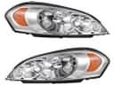 Chevrolet Headlight
 Chevrolet Tail Light
 Chevrolet Back Up Light
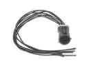 Chevrolet Body Wiring Harness Connector
 Chevrolet Chassis Wiring Harness Connector
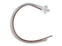 Chevrolet Door Lock Switch Connector
 Chevrolet Fog Light Bulb
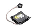 Chevrolet Hid Bulb Ballast
 Chevrolet Interior Light Bulb
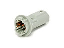 Chevrolet Light Socket
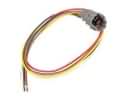 Chevrolet Rear Light Harness Connector
 Chevrolet Speaker Connector
Browse Chevrolet Light Control Module by Models
S10 Tahoe Camaro Impala Silverado 1500 Caprice Blazer Tracker Spark Trax Trailblazer Astro Corvette Aveo Beretta C1500 C2500 C3500 Corsica Express 1500 Express 2500 Express 3500 G30 K1500 K2500 K3500 Lumina Metro Monte Carlo P30 Venture Lumina APV Suburban 1500 Aveo5 C1500 Suburban C2500 Suburban K1500 Suburban K2500 Suburban Silverado 1500 LTD Suburban 2500