ChevyParts
My Garage
My Account
Cart
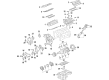
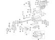
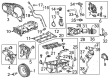
OEM Chevrolet Oil Pump
Oil Fluid Pump- Select Vehicle by Model
- Select Vehicle by VIN
Select Vehicle by Model
orMake
Model
Year
Select Vehicle by VIN
For the most accurate results, select vehicle by your VIN (Vehicle Identification Number).
74 Oil Pumps found


Chevrolet Oil Pump Part Number: 93427692
$128.19 MSRP: $201.71You Save: $73.52 (37%)Ships in 1-3 Business DaysProduct Specifications- Other Name: Pump, Oil; Water Pump; Pump Assembly; Pump, Engine Oil Pump
- Replaces: 12555884, 03848907, 3848907, 12555284

Chevrolet Oil Pump Part Number: 55508996
$120.19 MSRP: $189.07You Save: $68.88 (37%)Ships in 1-2 Business DaysProduct Specifications- Other Name: Pump, Engine Oil Pump; Oil Pump Repair Kit
- Replaced by: 40009011

Chevrolet Pump Assembly Part Number: 24043459
$207.32 MSRP: $326.14You Save: $118.82 (37%)Ships in 1-3 Business DaysProduct Specifications- Other Name: Pump Assembly-Automatic Transmission Fluid (W/O Drvtrn & Filter); Pump, Transmission Oil Pump

Chevrolet Pump Assembly Part Number: 24285095
$243.43 MSRP: $386.51You Save: $143.08 (38%)Ships in 1-2 Business DaysProduct Specifications- Other Name: Pump Assembly-Automatic Transmission Fluid
- Replaces: 24280347
Chevrolet Pump Assembly Part Number: 24042236
$180.32 MSRP: $283.72You Save: $103.40 (37%)Ships in 1-3 Business DaysProduct Specifications- Other Name: Pump Assembly-Automatic Transmission Fluid (W/O Filter & Drvt*N); Pump, Transmission Oil Pump
- Replaced by: 24052579

Chevrolet Oil Pump Part Number: 12696175
$279.00 MSRP: $438.88You Save: $159.88 (37%)Ships in 1-3 Business DaysProduct Specifications- Other Name: Pump, Engine Oil Pump; Oil Pump Repair Kit; Engine Oil Pump
- Replaces: 12686519, 12696028, 12676147, 12679427, 12681586

Chevrolet Oil Pump Part Number: 55489202
$94.10 MSRP: $147.39You Save: $53.29 (37%)Product Specifications- Other Name: Pump, Engine Oil Pump; Oil Pump Repair Kit

Chevrolet Oil Pump Part Number: 55509127
$278.21 MSRP: $437.75You Save: $159.54 (37%)Product Specifications- Other Name: Pump Assembly-Oil & Power Brake Booster; Oil Pump Repair Kit; Pump, Engine Oil Pump
- Replaces: 55487858
Chevrolet Oil Pump Part Number: 12731661
$86.37 MSRP: $135.27You Save: $48.90 (37%)Product Specifications- Other Name: Pump, Engine Oil Pump
- Replaces: 12698354, 12689919
Chevrolet Oil Pump Part Number: 12695661
$109.49 MSRP: $171.47You Save: $61.98 (37%)Ships in 1-3 Business DaysProduct Specifications- Other Name: Pump, Engine Oil Pump; Oil Pump Repair Kit
Chevrolet Oil Pump Part Number: 12705142
$127.48 MSRP: $200.53You Save: $73.05 (37%)Ships in 1-3 Business DaysProduct Specifications- Other Name: Pump, Engine Oil Pump; Oil Pump Repair Kit
Chevrolet Oil Pump Part Number: 25202388
$110.99 MSRP: $173.82You Save: $62.83 (37%)Ships in 1-3 Business DaysProduct Specifications- Other Name: Pump, Engine Oil Pump; Oil Pump Repair Kit

Chevrolet Pump Assembly Part Number: 24042244
$229.32 MSRP: $360.83You Save: $131.51 (37%)Ships in 1-2 Business DaysProduct Specifications- Other Name: Pump Assembly-Automatic Transmission Fluid (W/O Filter & Drvtrn); Pump, Transmission Oil Pump
- Replaced by: 24052581
Chevrolet Oil Pump Part Number: 12707324
$334.30 MSRP: $525.88You Save: $191.58 (37%)Ships in 1-3 Business DaysProduct Specifications- Other Name: Pump, Engine Oil Pump; Oil Pump Repair Kit
- Replaces: 12699269
Chevrolet Oil Pump Part Number: 12696174
$341.38 MSRP: $537.02You Save: $195.64 (37%)Ships in 1-3 Business DaysProduct Specifications- Other Name: Pump, Engine Oil Pump; Oil Pump Repair Kit
- Replaced by: 12741263
- Replaces: 12683664, 12687893, 12668981, 12666625

Chevrolet Oil Pump Part Number: 12674460
$118.10 MSRP: $201.05You Save: $82.95 (42%)Ships in 1-2 Business DaysProduct Specifications- Other Name: Pump, Engine Oil Pump; Oil Pump Repair Kit
- Replaces: 12627211
Chevrolet Oil Pump Part Number: 12678605
$426.71 MSRP: $726.46You Save: $299.75 (42%)Ships in 1-3 Business DaysProduct Specifications- Other Name: Pump, Engine Oil Pump; Oil Pump Repair Kit
- Replaced by: 12686435

Chevrolet Oil Pump Part Number: 14091485
$139.21 MSRP: $219.02You Save: $79.81 (37%)Product Specifications- Other Name: Pump, Engine Oil; Oil Pump Repair Kit; Pump, Engine Oil Pump
Chevrolet Oil Pump Part Number: 12728436
$957.47 MSRP: $1512.98You Save: $555.51 (37%)Ships in 1-3 Business DaysProduct Specifications- Other Name: Pump Kit-Oil; Pump Kit, Engine Oil Pump
- Replaced by: 12734323

Chevrolet Oil Pump Part Number: 55584330
$177.56 MSRP: $279.38You Save: $101.82 (37%)Product Specifications- Other Name: Pump, Engine Oil Pump; Oil Pump Repair Kit; Engine Oil Pump
| Page 1 of 4 |Next >
1-20 of 74 Results
Chevrolet Oil Pump
Want to cut long-term maintenance and repair costs? Choose OEM Oil Pump. Those parts deliver top durability you can trust. On our site, you'll find a huge catalog of genuine Chevrolet parts. Prices are unbeatable, so you can keep more in your pocket. Every OEM Chevrolet Oil Pump includes a manufacturer's warranty. You can also get an easy return policy that keeps buying risk free. Fast delivery, get your car on the road quickly. It's simple to search, compare, and order. Stop guessing about quality or fit. Order today and save with parts that last.
Chevrolet Oil Pump Parts Questions & Experts Answers
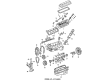
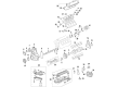
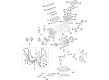
- Q: What precautions should be taken when servicing the oil pump to prevent damage to oil seals on Chevrolet Aveo?A:When maintaining the fluid pump, be very careful when handling oil seals as only slight damage to the lip of a seal may cause leakage of oil. First, rotate the drive gear using 2 screwdrivers so that it spins smoothly without letting the driver fall because it may get detached from the stator shaft. Then, take out the 8 bolts and the stator shaft, and then Oil Pump drive gear and oil shaft from Oil Pump body.
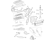
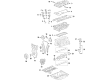
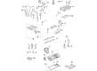
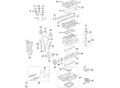
- Q: How to replace the oil pump on Chevrolet Impala?A:You should start the Oil Pump replacement by taking off the case side cover. Use a flat-bladed tool next to disconnect all the electrical connectors from the solenoid valves, the tfp switch, and the temperature sensor. Make sure you do not take out bolt (205) that holds the Oil Pump in place. Now, take out the Oil Pump bolts (206, 207) and lift the Oil Pump (200) from the Valve Body (300) so you can inspect it. Once you have the Oil Pump ready, put it back into the Valve Body (300) according to the fastener notice in service precautions. Put the Oil Pump bolts (206, 207) in place and tighten them; use 12 nm (106 inch lbs.) for the 207 bolts and 16 nm (12 ft. Lbs.) for the connect the electrical wiring to the solenoid valves (315A, 315B, 322, 334, and 440), the tfp manual valve position switch (395), and the temperature sensor (391), before putting on the case side cover.
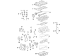
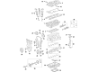
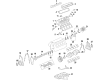
- Q: How to replace the oil pump on Chevrolet Monte Carlo?A:You must begin by taking off the case side cover to change the oil pump. Settling a flat tool disconnects power supplies from the solenoid valves (315A, 315B, 322, 334, 440), TFP manual position switch (395), and temperature probe (391). The oil pump needs to stay on its bolt but you must extract both its bolts (206 and 207) then pull out the oil pump (200) from valve body (300). Install the oil pump (200) properly into valve body (300) and fasten oil pump bolts (206 and 207). Be sure to follow the Fastener Notice on service precautions. Securely tighten both M6 X 1.0 X 85 bolts 207 to 12 Nm and M6 X 1.0 X 95 bolts 206 to 16 Nm. Reattach all electrical connectors to their respective locations including solenoid valves 315A, 315B, 322, 334, and 440 together with manual valve position switch 395 and temperature sensor 391 before installing the case side coveribly.


Related Chevrolet Parts
 Chevrolet Camshaft
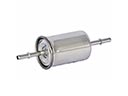 Chevrolet Fuel Filter
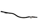 Chevrolet Dipstick Tube
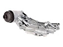 Chevrolet Oil Cooler
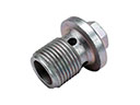 Chevrolet Drain Plug
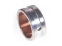 Chevrolet Balance Shaft Bearing Set
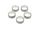 Chevrolet Camshaft Bearing
 Chevrolet Camshaft Seal
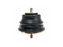 Chevrolet Engine Mount
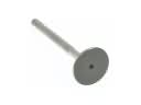 Chevrolet Exhaust Valve
 Chevrolet Timing Chain Tensioner
 Chevrolet Valve Cover Gasket
Browse Chevrolet Oil Pump by Models
Nova S10 Colorado C10 Tahoe Cruze Malibu Camaro Equinox Impala SS SSR Avalanche Silverado 1500 Silverado 2500 HD Caprice Suburban Traverse Blazer Tracker Volt El Camino K10 Spark Trax Trailblazer Astro Cavalier Corvette C20 Aveo Beretta C1500 C2500 C30 C3500 Celebrity Corsica Express 1500 Express 2500 Express 3500 G10 G20 G30 K1500 K20 K2500 K30 K3500 Lumina Metro Monte Carlo Prizm S10 Blazer Uplander Venture Lumina APV Silverado 3500 Suburban 1500 Trailblazer EXT Avalanche 2500 Aveo5 C1500 Suburban C2500 Suburban Captiva Sport Impala Limited K1500 Suburban K2500 Suburban R20 R30 Silverado 1500 Classic Silverado 1500 LD Silverado 1500 LTD Silverado 2500 HD Classic Silverado 3500 Classic Silverado 3500 HD Spectrum Suburban 2500 Suburban 3500 HD V20 V30