ChevyParts
My Garage
My Account
Cart
OEM GMC Sierra 1500 Fuel Injector
Gas Injector- Select Vehicle by Model
- Select Vehicle by VIN
Select Vehicle by Model
orMake
Model
Year
Select Vehicle by VIN
For the most accurate results, select vehicle by your VIN (Vehicle Identification Number).
26 Fuel Injectors found


GMC Sierra 1500 Injector Part Number: 12594512
$73.36 MSRP: $149.00You Save: $75.64 (51%)Ships in 1-2 Business Days


GMC Sierra 1500 Injector Part Number: 12609749
$73.20 MSRP: $148.68You Save: $75.48 (51%)Ships in 1-2 Business Days

GMC Sierra 1500 Injector Part Number: 12580426
$107.23 MSRP: $217.78You Save: $110.55 (51%)Ships in 1-2 Business Days

GMC Sierra 1500 Injector Part Number: 19420316
$78.14 MSRP: $139.52You Save: $61.38 (44%)Ships in 1 Business Day


GMC Sierra 1500 Injector Part Number: 12710481
$69.60 MSRP: $141.40You Save: $71.80 (51%)
GMC Sierra 1500 Injector Part Number: 12732622
$116.07 MSRP: $208.20You Save: $92.13 (45%)Ships in 1-2 Business DaysGMC Sierra 1500 Injector Part Number: 12733960
$46.29 MSRP: $94.02You Save: $47.73 (51%)Ships in 1-2 Business Days
GMC Sierra 1500 Injector Part Number: 12613411
$81.23 MSRP: $172.82You Save: $91.59 (53%)Ships in 1-2 Business DaysGMC Sierra 1500 Injector Part Number: 55506244
$199.37 MSRP: $404.92You Save: $205.55 (51%)Ships in 1-3 Business Days
GMC Sierra 1500 Injector Part Number: 12732623
$60.77 MSRP: $108.52You Save: $47.75 (44%)
GMC Sierra 1500 Injector Part Number: 17113698
$112.36 MSRP: $228.20You Save: $115.84 (51%)GMC Sierra 1500 Injector Part Number: 17113553
$73.17 MSRP: $228.30You Save: $155.13 (68%)Ships in 1-2 Business Days
GMC Sierra 1500 Injector Part Number: 19420317
$68.92 MSRP: $139.99You Save: $71.07 (51%)GMC Sierra 1500 Injector Part Number: 88894353
$120.24 MSRP: $244.20You Save: $123.96 (51%)Ships in 1-2 Business DaysGMC Sierra 1500 Injector Part Number: 12690934
$38.83 MSRP: $109.30You Save: $70.47 (65%)Ships in 1-2 Business Days
GMC Sierra 1500 Injector Part Number: 97729095
$274.91 MSRP: $543.11You Save: $268.20 (50%)Ships in 1-3 Business Days
GMC Sierra 1500 Injector Part Number: 97780474
$486.29 MSRP: $963.93You Save: $477.64 (50%)Ships in 1-3 Business Days
GMC Sierra 1500 Injector Part Number: 97780144
$422.63 MSRP: $837.17You Save: $414.54 (50%)


GMC Sierra 1500 Injector Part Number: 12684125
GMC Sierra 1500 Injector Part Number: 12720121
$104.03 MSRP: $162.94You Save: $58.91 (37%)
| Page 1 of 2 |Next >
1-20 of 26 Results
GMC Sierra 1500 Fuel Injector
Want to cut long-term maintenance and repair costs? Choose OEM Fuel Injector. Those parts deliver top durability you can trust. On our site, you'll find a huge catalog of genuine GMC Sierra 1500 parts. Prices are unbeatable, so you can keep more in your pocket. Every OEM GMC Sierra 1500 Fuel Injector includes a manufacturer's warranty. You can also get an easy return policy that keeps buying risk free. Fast delivery, get your car on the road quickly. It's simple to search, compare, and order. Stop guessing about quality or fit. Order today and save with parts that last.
GMC Sierra 1500 Fuel Injector Parts Questions & Experts Answers
- Q: How to replace the fuel injectors on GMC Sierra 1500?A:The air cleaner outlet duct must be removed carefully before the replacement can start. Begin the fuel system pressure relief operation with ch-48027 or perform it without the tool then remove the engine wiring harness bracket nut. Next disconnect the electrical connectors from the evap purge solenoid, generator, MAP Sensor, ignition coil main electrical connector and the fuel injectors. First mark each connector for later assembly before you move the cpa retainer with one click and press the tab to disconnect the Fuel Injector electrical connectors. Above the electronic throttle control device and Fuel Injector suite disconnect the electrical connectors while using the standard marking procedures. Uninstall those engine wiring harness clips which support the generator battery jumper cable and ignition coil bracket stud . Remove negative battery cable stud and terminals (2 and 3) from the Cylinder Head. First disconnect the wiring harness clip bolt from the generator bracket then place the harness aside while also removing the chassis fuel feed pipe quick connect fitting from the Fuel Rail. Lift out the evap purge solenoid from its position on the Fuel Rail by removing the bolts after unhitching evap tube fasteners at both the intake manifold and evap purge solenoid. Detach the Fuel Rail assembly while taking care not to harm either the injector electrical connector terminals or spray tips and apply caps over each fitting to stop any contamination. Evacuate all injectors from their bores while lifting the Fuel Rail in an even manner after cleaning it as needed. The installation of fuel injectors requires removing their retainers in combination with injectors and discarding the o-ring seals that sit at positions 2 and 4. First clean the engine oil to lubricate the new o-ring seals before attaching them to the injectors and installing the injectors into the Fuel Rail with retainers in place. After applying lubrication to the lower o-ring seals install the Fuel Rail onto the intake manifold while applying firm downward pressure until it reaches a complete position. First tighten 10 nm (89 lb in) Fuel Rail bolts before reinstalling the evap tube along with purge solenoid and making quick connect fittings to the evap canister and intake manifold. First reattach the Fuel Rail to the chassis feed pipe. After that, install the pcv hose before gathering all engine wiring harnesses over the engine. Take the generator bracket as the installation site for the wiring harness clip while tightening its clip bolt to 9 nm (80 lb in). Reinstall the negative battery cable stud on the right Cylinder Head unit while fastening it with 25 nm torque setting (18 lb ft). One should first reconnect the ignition coil main electrical connector then install the cpa retainer. Seed the electronic throttle control and Fuel Injector electrical connectors before tightening the cpa retainer. Fasten the engine wiring harness bracket nut with 5 nm (44 lb in) torque. After that, connect the MAP Sensor , generator and evap purge solenoid connectors followed by engine harness bracket assembly. Turn the ignition to on then off starting with two seconds of on time followed by ten seconds of off time before repeating the on step to check for any fluid leakage. Inspect for any leaks. Reinstall the air cleaner outlet duct at the end of the installation procedure.

Related GMC Sierra 1500 Parts
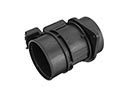 GMC Sierra 1500 Mass Air Flow Sensor
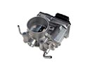 GMC Sierra 1500 Throttle Body
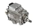 GMC Sierra 1500 Fuel Injection Pump
 GMC Sierra 1500 Fuel Injector O-Ring
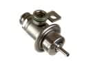 GMC Sierra 1500 Fuel Pressure Regulator
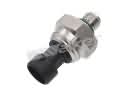 GMC Sierra 1500 Fuel Pressure Sensor
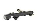 GMC Sierra 1500 Fuel Rail
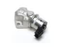 GMC Sierra 1500 Idle Control Valve
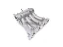 GMC Sierra 1500 Intake Manifold
 GMC Sierra 1500 PCV Valve Hose
 GMC Sierra 1500 Throttle Body Gasket
 GMC Sierra 1500 Turbocharger