
Popular OEM Chevrolet Suburban 2500 Parts
- Body & Hardware Parts View More >
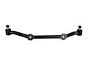
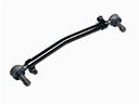
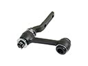
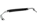
- Steering Parts View More >
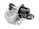
- Electrical Parts View More >
- Air & Fuel Delivery Parts View More >
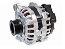
- Charging & Starting Parts View More >
- Engine Parts View More >
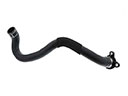
- Belts & Cooling Parts View More >
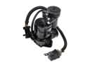
- Suspension Parts View More >
- Driveline & Axles Parts View More >
- Emission Control & Exhaust Parts View More >
- Transmission Parts View More >
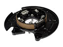
- Brakes Parts View More >


Why Buy Genuine Chevrolet Suburban 2500 Parts From ChevyPartsGiant.com
Looking for real Chevrolet Suburban 2500 parts? ChevyPartsGiant.com may be a better choice to find genuine parts at wallet-friendly prices. We sell only OEM Chevrolet Suburban 2500 parts, ensuring perfect fit, reliability, and long-term performance. With our website, you can easily get access to the same parts found at local Chevrolet stores. All components are produced by Chevrolet and are exclusively fitted on Chevrolet Suburban 2500 automobiles. By shopping at our store, you can enjoy the quality of the Chevrolet factory without the high prices of brick-and-mortar facilities. We achieve this because we are an online store operating at lower costs, which we pass on to you. We also have a user-friendly platform where you can find and order genuine Chevrolet Suburban 2500 parts swiftly. We are here to make your process of restoring a Chevrolet Suburban 2500 or dealing with simple repairs quick and inexpensive. We also make it easy to obtain Chevrolet Suburban 2500 parts at competitive shipping prices and a team of knowledgeable staff ready to take your order. Choose ChevyPartsGiant.com to save time and money, as well as keep your Chevrolet Suburban 2500 in the good condition.
Since 1935 the Chevrolet Suburban 2500 3/4-tonne SUV has matured through successive development to satisfy both family demands and occupational needs. The Chevrolet Suburban 2500 features a 7.4L V8 powertrain that provides strong performance for towing needs and hauling and it uses a heavy-duty 4L80 four-speed automatic transmission engineered for diesel power plants. Both gasoline and diesel engine models of the Chevrolet Suburban 2500 feature the durable 4L80-E transmission for smooth performance and reliable gear transitions. The Suburban 2500 features control systems that let drivers adjust between 2WD and 4WD operational modes depending on outdoor conditions. The implementation of all-electric cooling in 2005 made motors more efficient by cutting down power wastage which lowered fuel usage. Amajor improvement comes from the independent rear suspension which produces greater ride quality because it efficiently takes in road bumps compared to earlier fixed axle systems. The Suburban 2500 is known for its towing capabilities, with a maximum towing capacity of up to 8,100 lbs (approximately 3,670 kg), making it an excellent choice for hauling large trailers and equipment. The Chevrolet Suburban 2500 received updates to its inside and outside sections where manufacturers incorporated features like trailer braking control alongside comfort system enhancements. Using original equipment manufacturer Chevrolet Suburban 2500 parts for maintenance allows vehicle owners to maintain the designed performance and reliability because such authentic components reach exacting standards of quality established by Chevrolet.
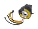
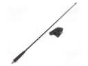
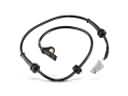
Chevrolet Suburban 2500 concerns cluster into fuel delivery, drivetrain control, and braking electronics. In the fuel system, the Suburban 2500 may stall or refuse to start. A weakening fuel pump overheats, then loses pressure during climbs or hot idle. Replacing the fuel filter on schedule protects the Suburban 2500 from premature pump failure. Chevrolet drivetrain control can also fault and trigger a service 4WD message. The Suburban 2500 often needs a transfer case position sensor after encoder wear. Selector switch contacts can misreport range, confusing the control module. Scan the module, confirm codes, and verify wiring before component replacement. For braking electronics, the Suburban 2500 may show a persistent ABS light. A failing Chevrolet front wheel speed sensor can cause erratic low speed activation. Inspect sensor air gap and hub corrosion, then clean or replace as needed. After repairs, the Suburban 2500 should complete a road test and relearn procedures. Chevrolet service schedules also recommend fuel quality checks and updated calibrations. These steps keep your Chevrolet Suburban 2500 dependable under heavy towing and daily errands. Finish by checking battery voltage, ground integrity, and module connectors for moisture intrusion.
Chevrolet Suburban 2500 Parts Questions & Answers
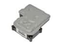
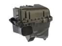
- Q: How to replace the underhood fuse box on Chevrolet Suburban 2500?A:Begin electrical junction block or underhood electrical center replacement by disconnecting the negative Battery Cable followed by removal of the left fender upper brace. The electrical center brace cover assembly requires lifting outward to release its tabs so you can remove all fuses and relays. Use the tab to rotate the electrical center onto its studs at before removing all connectors by unscrewing their bolt . All electrical center block connectors should be removed before pushing up on the tabs which will lift the electrical center outside the housing. Replace the starting and charging center bracket by first removing its 4 retaining bolts followed by taking off the bracket assembly from the fender. Use the front fender to mount the starting and charging center bracket assembly and proceed by tightening its 4 retaining bolts to 9 n.m (80 lb in). Position the electrical center block stubs into their corresponding slots before the tabs secure it in place; then connect wire connectors to the lower segment of the electrical center block and tighten all connector bolts to 9 n.m (80 lb in). Secure all wire connectors firstly and position the electrical center block correctly until its tabs firmly lock into position. First install the lower part of the cover while following all Fuse and relay locations to install each component before putting on the cover. Secure the fender upper brace and fasten its 4 retaining bolts to 25 n.m (18 lb ft). Complete the check by attaching the negative Battery Cable and starting the vehicle which allows testing of all integrated systems.
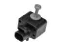
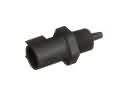
- Q: How to replace the throttle body assembly and handle the electronic throttle control components on Chevrolet Suburban 2500?A:To change the Throttle Body assembly, handle the electronic throttle control components with care not to damage, avoid dropping it or slap them around, do not immerse it in any cleaning solvents. The electronic throttle control (ETC) means throttle position (TP) sensor is not serviceable individually; there is the need to service both components as one assembly unit. Start by identifying the 8 digit part identification stamp on the Throttle Body casting for future reference in the event of replacement. Remove the air induction assembly and make sure that in doing so, any openings are covered or plugged to prevent contamination. Pull off the throttle actuator motor harness connector and the tp sensor harness connector, and the Throttle Body attaching nuts after cautioning against reusing the Throttle Body Gasket, which should also be discarded. Replace a new Throttle Body Gasket and the Throttle Body assembly, wherein the Throttle Body nuts would be tightened using a torque wrench to a point of 10 n.m (89 lb in). Make sure the electrical connector to the Throttle Body motor and the connector seal are in good condition. Reconnect the tp sensor harness connector, and the throttle actuator motor harness; reconnect and reinstall the air induction assembly. With the vehicle not in reduced engine power, turn the ignition with the engine off to check the throttle complete positions for open and closure by the use of a scan tool which will check the throttle angles as you operate the accelerator pedal to ensure that it is operating free of binding in between closed throttle to full open throttle (WOT). Finally, start the engine.
- Q: How to service and repair the oil filter and replace the engine on Chevrolet Suburban 2500?A:You need the following tools to service and repair the Oil Filter while replacing the engine: engine lift brackets (J 36857). Engine lift brackets (J 36857). Place fender covers on both fenders after you open the hood and then lift the hood to its service position. The hood hinge bolts need removal before you raise the hood to its vertical position and install the bolts into its service position until it reaches proper tightness. First disconnect both the positive and negative battery cables before unclamping the Throttle Body and air cleaner and removing the air cleaner outlet duct. Wrench off the ignition coils then pressure off the fuel system and disconnect the fuel feed pipeline (1) and return pipeline (2) from the Fuel Rail. Start by taking out the air conditioning (A/C) compressor then follow with Radiator removal and next disconnect the throttle actuator control (TAC) module electrical connector along with vacuum lines followed by the exhaust gas recirculation (EGR) valve adapter while you also take out the ground cable bolt at the engine block and remove the generator and engine electrical harness before elevating the vehicle with safety stands. First remove the Starter motor and Power Steering Pump hoses and then disconnect the exhaust manifold pipe along with the Catalytic Converter and torque converter bolts and transmission bolt. Install the engine lift brackets (J 36857) to the rear of the right Cylinder Head and the front of the left Cylinder Head and secure them with gm P/N 9428217 and gm P/N 15650963 while tightening the bolts to 40 nm (30 ft. Lbs). Use a suitable lifting device to extract the engine by first removing the engine mount heat shield bolts and shields together with engine mount to engine mount bracket bolts. Lay the engine on a suitable stand before removing the generator bracket and A/C Compressor bracket and power steering bracket from the Cylinder Head. The next step will be to detach the lift brackets from the Cylinder Head. Attach the engine lift brackets (J 36857) to re-install the attaching bolt and washer using gm P/N 9428217 with gm P/N 15650963 while tightening the lift bracket bolts to 40 nm (30 ft. Lbs.). You should install the engine block mounted A/C Compressor/power steering mounting bracket with Power Steering Pump bracket bolts and nut torqued to 50 nm (37 ft. Lbs.) then tighten the generator bracket. The lifting device should be used to remove the engine before installation into the vehicle. The engine mount installation process includes mounting the engine mount to engine mount bracket bolts followed by engine mount heat shield and bolts then removing the engine lift hooks from the cylinder heads. Start by supporting the vehicle with safety stands after you raise it and then proceed to install the engine oil cooler lines on the engine block followed by bolts connecting engine to transmission and torque converter bolts and Catalytic Converter and exhaust manifold pipe and Power Steering Pump hoses and Starter motor. Handle the vehicle descent before putting the generator into position with the engine block ground cable connection followed by a 16 nm (12 ft. Lbs.) bolt torque on the engine wiring harness. Follow this installation sequence: connect the tac module electrical connector then install vacuum lines to the engine block and egr valve adapter and Radiator and positive and negative battery cables and lastly the A/C Compressor and ignition coils. After tightening the air cleaner outlet duct clamps the removal of fender covers should occur followed by lowering the hood to its normal position before installing and tightening hood hinge bolts to 25 nm (18 ft. Lbs.). Begin your engine start procedure by adding recommended oil of the right grade and quantity and use gm U.S. P/N 1052367, canada P/N 992869 or their equivalent. Start the engine by cranking then remove it from idle until you see oil pressure readings appear. After clear audible checks for noise or part bindings the technician will place the fuel pump Fuse back in the position and reconnect coil harness connectors to initiate engine start-up. The procedure includes another round of listening for abnormal sounds. Check the oil pressure with either the vehicle's built-in gauge or an external oil pressure gauge and maintain engine rpm at 1000 while it warms up to normal operating temperature. Afterward inspect for leaks from oil and coolant and perform a final check of engine liquids. Finish up with a crankshaft position (CKP) sensor variation learn procedure.
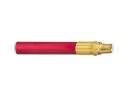
- Q: How to replace the right exhaust manifold on Chevrolet Suburban 2500?A:Place your attention on replacing the right Exhaust Manifold by starting with the wheelhouse panel removal along with the oil level indicator tube. Twist each Spark Plug boot one-half turn to free it before you pull on the boot and remove the Spark Plug Wires from their installations. The replacement process starts with removing the spark plugs before proceeding to take off exhaust gas recirculation (EGR) pipe nuts from the Exhaust Manifold and the egr pipe bracket bolt. Discard the egr pipe gasket during this stage. First, elevate the vehicle while providing support then detach the egr pipe from its position before removing Exhaust Manifold heat shield fasteners and its shielding component. Lower the vehicle while proceeding to take out Exhaust Manifold bolts and nuts before removing the manifold together with the gasket. The manifold should be cleaned before inspection to determine whether it needs reuse. First install the new Exhaust Manifold Gasket before installing the Exhaust Manifold and tighten the bolt to 35 nm (26 ft. Lbs.) while the nuts require a torque of 16 nm (12 ft. Lbs.). Afteriness the vehicle another time to put the heat shield into place with its securing bolts and nuts then tightening them to 25 nm (18 ft. Lbs.). Position the egr then install a new egr pipe gasket while connecting the egr pipe bracket bolt with 50 nm (37 ft. Lbs.) tension and the egr pipe nuts to the Exhaust Manifold at 30 nm (22 ft. Lbs.). The last step includes attaching the spark plugs by verifying complete wire boot seating with repeated boot end pressure then reattaching wires to plugs and coils and reinstalling the oil level indicator tube before fitting the wheelhouse panel.


