
Popular OEM GMC Sierra 3500 Classic Parts
- Body & Hardware Parts View More >
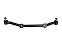
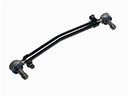
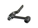
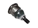
- Steering Parts View More >
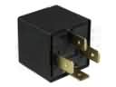
- Electrical Parts View More >
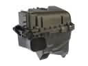
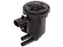
- Air & Fuel Delivery Parts View More >
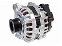
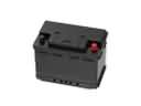
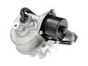
- Charging & Starting Parts View More >
- Engine Parts View More >
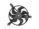
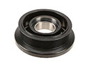
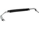
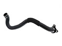
- Belts & Cooling Parts View More >
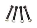
- Suspension Parts View More >
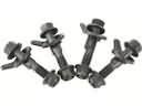
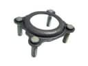
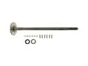
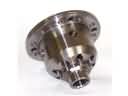
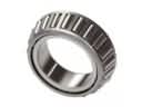
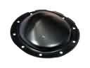
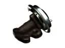
- Driveline & Axles Parts View More >
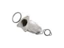
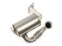
- Emission Control & Exhaust Parts View More >
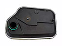
- Transmission Parts View More >
- Brakes Parts View More >

Why Buy Genuine GMC Sierra 3500 Classic Parts From ChevyPartsGiant.com
Looking for real GMC Sierra 3500 Classic parts? ChevyPartsGiant.com may be a better choice to find genuine parts at wallet-friendly prices. We sell only OEM GMC Sierra 3500 Classic parts, ensuring perfect fit, reliability, and long-term performance. With our website, you can easily get access to the same parts found at local GMC stores. All components are produced by GMC and are exclusively fitted on GMC Sierra 3500 Classic automobiles. By shopping at our store, you can enjoy the quality of the GMC factory without the high prices of brick-and-mortar facilities. We achieve this because we are an online store operating at lower costs, which we pass on to you. We also have a user-friendly platform where you can find and order genuine GMC Sierra 3500 Classic parts swiftly. We are here to make your process of restoring a GMC Sierra 3500 Classic or dealing with simple repairs quick and inexpensive. We also make it easy to obtain GMC Sierra 3500 Classic parts at competitive shipping prices and a team of knowledgeable staff ready to take your order. Choose ChevyPartsGiant.com to save time and money, as well as keep your GMC Sierra 3500 Classic in the good condition.
The GMC Sierra 3500 Classic entered the market as a significant GMC model with basic features from prior models alongside major updated elements. Among the powerful engine options available was the 6.6L Duramax turbo-diesel V8, delivering 360 horsepower and 650 lb-ft of torque. An upgraded Allison six-speed automatic transmission connects to the motor since it delivers improved highway fuel efficiency while maintaining smooth driving power. All V8 engine choices were offered during the manufacturing period of the GMC Sierra 3500 Classic. Before the 2007 Classic model the Vortec V8 8.1-liter was the top displacement engine offered by the manufacturer. Proper equipment enables the GMC Sierra 3500 Classic to tow up to 23,300 pounds while its typical payload weight reaches about 5,300 pounds. Three body combinations consisting of standard and extended and crew cab form an option set for GMC Sierra 3500 Classic models which can operate with rear-wheel drive or complete all-wheel drive systems. The GMC Sierra 3500 Classic design includes dual rear wheels as a feature for heavy load hauling alongside a smooth riding experience during tough terrain conditions. Selecting GMC Sierra 3500 Classic genuine parts delivers dependable operation while the manufacturing standards along with warranty ensure both reliability and performance.
The GMC Sierra 3500 Classic trucks have three problems classified under transmission, rear axle, and brake hydraulics. Allison 1000 on a Sierra 3500 Classic can skip when shifting, or go into limp mode. Friction, debris, and rubbing of the valve body walls decrease the pressure and the clutch capacity. Fluid exchange, filter replacement, and checks to GMC line pressure specifications are included. Repair the valve body and solenoids, and consider a rebuild to HD parts when damage is present. A Sierra 3500 Classic can drip gear oil on wheels or drums in the axle. A damaged pinion seal or abrasion of the rear axle hub seals allows fluid losses and contamination. Replace pinion seal, hub seals, set bearing preload, and check backlash. Inspect the Sierra 3500 Classic after parking it overnight and check that there is no seepage. In brakes, corrosion could make brake lines of Sierra 3500 Classic soft and lead to breaking. Strong rust is capable of tearing up lines under hard stops. Replace all of the brake lines with NiCopp, flush the system, and bleed each circuit. Observation of GMC intervals, GMC approved fluids, as well as recording scan data after each repair. Inspect the Sierra 3500 Classic and ensure smooth shifts, dry hubs, and a firm pedal.
GMC Sierra 3500 Classic Parts Questions & Answers
- Q: How to replace a two-piece drive shaft on GMC Sierra 3500 Classic?A:Start the two-piece propeller shaft replacement process by acquiring clamp pliers with narrow jaw functionality (J 43218). Begin by elevating the vehicle while you make notice marks on all driveline components starting from the rear propeller shaft to its pinion yoke connection on the rear axle and extending to the front propeller shaft attachment on transmission or Transfer Case. Start by using the clamp pliers - narrow jaw (J 43218) to remove clamps securing the boot fastener at both ends of the front propeller shaft stub shaft and the rear propeller shaft Slip Yoke by lifting their exposed edges. The next step requires you to separate bolts and yoke retainers from the rear axle pinion yoke. Use careful movements to pull the rear propeller shaft in forward direction away from the rear axle pinion yoke before rotating it backwards from the front propeller shaft stub shaft until it can be pulled from the vehicle. The front propeller shaft stub shaft boot needs to be removed first while the center bearing support nuts and center bearing support can be uninstalled next. The front propeller shaft installation requires a slide toward the transmission or Transfer Case for vehicles not equipped with rpo mw7 while vehicles with this feature need the shaft connected to the transmission pinion yoke. Reposition the reference marks created in the removal phase before securing bolts without applying torque. Position the center bearing support while torquing its nuts to 40 n.m (30 lb ft) then fasten the yoke retainer bolts to 25 n.m (18 lb ft). You should inspect the front propeller shaft stub shaft splines for proper grease lubrication; supply with chassis grease gm p/n 12377985 or equivalent for additional lubrication. Mount the boot along with two new clamps onto the front propeller shaft stub shaft when applicable. The last step includes connecting the rear propeller shaft Slip Yoke to the front propeller shaft stub shaft before installation of the rear propeller shaft onto the rear axle pinion yoke while keeping reference marks aligned. Conclude the repair by installing the yoke retainers and bolts while applying torque to 25 n.m (18 lb ft) on the yoke retainer bolts followed by boot clamp crimping with clamp pliers - narrow jaw (J 43218) until reaching the proper dimensions before returning the vehicle back down.
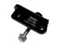
- Q: How to replace Knock Sensor 2 on GMC Sierra 3500 Classic?A:In order to replace Knock Sensor 2, remove first the right front wheel and tire. Then, from the wheel well open, disconnect the engine wiring harness electrical connector from the knock sensor. Then, take off the knock sensor bolt (739) and knock sensor (718). For mounting the knock sensor (718) screw to the engine block and mounting the knock sensor bolt (739) which tightened at a torque of 25 N.m (18 lb ft). Then attach the engine wiring harness connection to the knock sensor and install the right front wheel and tire back.
- Q: How to service and repair the steering linkage inner tie rod on GMC Sierra 3500 Classic?A:Service and repair of the steering linkage inner tie rod requires the removal of any present engine shield as the first step. First detach the steering linkage outer tie rod after removing the steering linkage inner tie rod from the relay rod by using the Inner Tie Rod Wrench (J 34028). First remove all oil, grease and other debris from the inner steering linkage tie rod then soak the threads with denatured alcohol until it dries. Soak the steering linkage inner tie rod threads with red LOCTITE(TM) threadlocker which means GM P/N 12345493 while Canadian P/N 10953488 performs the same function. Employ the Inner Tie Rod Wrench (J 34028) to install the steering linkage inner tie rod to the relay rod before securing it to 100 N.m (74 lb ft). As the last step reinstall the steering linkage outer tie rod followed by the engine shield if present and then adjust the front toe.
- Q: How to replace the left catalytic converter on a 6.0L Cab/Chassis on GMC Sierra 3500 Classic?A:The procedure to replace the left Catalytic Converter on a 6.0l cab/chassis begins by raising the vehicle with supports while also using a transmission jack for transmission support. The procedure starts by removing the transmission support nuts at the mount. After lifting the transmission off the support you need to remove its crossmember bolts and crossmember. Start by loosening the exhaust muffler clamp then remove any necessary muffler insulators to disconnect the pipe from the muffler with the help of a jack stand for muffler support. Start by taking off the connector position assurance (CPA) retainer attached to the left front heated Oxygen Sensor (HO2S) then unplug the engine wiring harness electrical connector which provides power to this left front ho2s unit. Begin by taking off the cpa retainer which leads to disconnection of the engine wiring harness electrical connector from the left rear ho2s electrical connector . Use a jack to lower the transmission slightly while removing the left Catalytic Converter to exhaust manifold nuts and then loosen the exhaust manifold pipe to exhaust manifold nuts. Installation of a new left Catalytic Converter requires the removal of ho2s sensors (1 and 4). Before installing, apply gm p/n 12377953 anti-seize compound or its equivalent to the old sensor threads before installing ho2s (1 and 4) and tightening to 42 n.m (31 lb ft). Use a transmitter lift to slightly raise the vehicle then secure the left Catalytic Converter to exhaust manifold nuts following a torque specification of 50 n.m (37 lb ft). Secure the exhaust manifold pipe to exhaust manifold nuts with a torque of 50 n.m (37 lb ft). Next, connect the engine wiring harness electrical connector to the left rear ho2s electrical connector. Finish by installing the cpa retainer to the left rear ho2s. Install the cpa retainer onto the left front ho2s then use the engine wiring harness electrical connector to connect to this ho2s device. Screw the exhaust muffler clamp with a torque of 47 n.m (35 lb ft) then replace any exhaust muffler insulators which were removed. Install the transmission support crossmember while removing the jack stand from beneath the muffler and use a torque wrench to tighten the crossmember bolts to 95 n.m (70 lb ft). Put the transmission onto the support then install the transmission mount to transmission support nuts which require a torque of 95 n.m (70 lb ft). Remove the support from the transmission after that lower the vehicle.


