
Popular OEM GMC Sierra 3500 Parts
- Body & Hardware Parts View More >
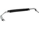
- Steering Parts View More >
- Electrical Parts View More >
- Air & Fuel Delivery Parts View More >
- Charging & Starting Parts View More >
- Engine Parts View More >
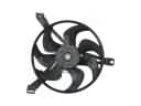
- Belts & Cooling Parts View More >
- Suspension Parts View More >
- Driveline & Axles Parts View More >
- Emission Control & Exhaust Parts View More >
- Transmission Parts View More >
- Brakes Parts View More >

Why Buy Genuine GMC Sierra 3500 Parts From ChevyPartsGiant.com
Looking for real GMC Sierra 3500 parts? ChevyPartsGiant.com may be a better choice to find genuine parts at wallet-friendly prices. We sell only OEM GMC Sierra 3500 parts, ensuring perfect fit, reliability, and long-term performance. With our website, you can easily get access to the same parts found at local GMC stores. All components are produced by GMC and are exclusively fitted on GMC Sierra 3500 automobiles. By shopping at our store, you can enjoy the quality of the GMC factory without the high prices of brick-and-mortar facilities. We achieve this because we are an online store operating at lower costs, which we pass on to you. We also have a user-friendly platform where you can find and order genuine GMC Sierra 3500 parts swiftly. We are here to make your process of restoring a GMC Sierra 3500 or dealing with simple repairs quick and inexpensive. We also make it easy to obtain GMC Sierra 3500 parts at competitive shipping prices and a team of knowledgeable staff ready to take your order. Choose ChevyPartsGiant.com to save time and money, as well as keep your GMC Sierra 3500 in the good condition.
Since its market introduction in 2000 the GMC Sierra 3500 has become a reliable one-ton truck for both work and leisure tasks through its robust frame system which enhances its loading abilities. The Sierra 3500 line includes either a high-output 6.6-liter gasoline V8 engine or a 6.6-liter Duramax turbo-diesel V8 engine package. The GMC Sierra 3500 ensures exceptional operational quality through its dual rear wheels and advanced suspension system which enables it to excel in construction and agricultural functions. This vehicle has a six-speed automatic transmission that helps with smooth gear shifts and high engine performance output to achieve better control in all driving conditions. Various updates have been implemented on the GMC Sierra 3500 since its launch with a major redesign in 2003 that brought both redesigned front-end assembly and cabin system enhancements for improved cabin use. Users benefit from the GMC MultiPro tailgate system because it provides various loading positions which simplify cargo operations. Genuine GMC Sierra 3500 parts follow exact factory specifications during their production to guarantee reliability together with performance. The extensive OEM parts catalog of GMC Sierra 3500 enables owners to retain their vehicle's original quality while enjoying manufacturer-supported guarantees and return assurance that enhances their reputation for enduring high-demand conditions.
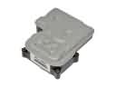
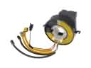
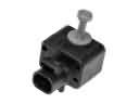
GMC Sierra 3500 concerns cluster into HVAC control, brake electronics, and engine ignition maintenance. On the Sierra 3500, failed AC mode door actuators misroute airflow and temperature. Scan the HVAC module for codes, replace the AC mode door actuator, then recalibrate. Another Sierra 3500 issue affects the braking electronics and battery health. A failing ABS control module can keep the pump running after shutdown. Replace the ABS control module, confirm grounds, and verify fuse integrity. For power delivery, the Sierra 3500 needs timely ignition service. Worn spark plugs and aging spark plug wires cause misfires and hard starting. Install new spark plugs and spark plug wires at 100,000 miles. After repairs, a GMC Sierra 3500 should idle smoothly and deliver stable power. Schedule regular inspections on the GMC Sierra 3500 to catch early faults. These steps keep a GMC Sierra 3500 reliable in heat, cold, and heavy use. Listen for clicking actuators during key on tests. Verify blend and mode door movement with bidirectional scan commands. If airflow remains wrong, inspect broken door shafts before reassembly. For the ABS fault, check pump relay control and harness corrosion. Spark service should include coil boots inspection and a careful gap check.
GMC Sierra 3500 Parts Questions & Answers
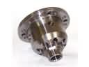
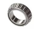
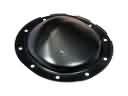
- Q: How to replace the inner wheel seal or bearing on the front drive axle on GMC Sierra 3500?A:The replacement of front drive axle inner axle seal or bearing requires these key tools: certain tools are necessary for this job: j 8092 universal driver handle (J 8092), j 2619-01 slide hammer (J 2619-01), j 29369-1 bushing and bearing remover (J 29369-1), j 29369-2 bushing and bearing remover (2-3 inch) (J 29369-2), j 36609 axle tube bearing installer (J 36609), and j 45225 axle seal installer (J 45225). J 8092 universal driver handle (J 8092), j 2619-01 slide hammer (J 2619-01), j 29369-1 bushing and bearing remover (J 29369-1), j 29369-2 bushing and bearing remover (2-3 inch) (J 29369-2), j 36609 axle tube bearing installer (J 36609), and j 45225 axle seal installer (J 45225). Perform this service by first lifting your vehicle while also draining the Differential carrier assembly fluids. Start by taking the inner Axle Shaft and housing assembly from the Differential carrier case followed by separating Clutch Fork assembly components and the inner Axle Shaft from the inner Axle Shaft housing for right side seal or bearing replacement. Place the inner Axle Shaft housing into a vise while securing it with clamp pressure centered on the mounting flange. To extract an inner Axle Shaft seal or bearing, use either j 29369-1 or j 29369-2 behind the seal or bearing as necessary then attach j 2619-01 to the specified bushing and bearing remover. To replace the left side seal properly mark the correct wheel drive shaft and inner Axle Shaft alignment before disconnecting the wheel drive shaft followed by inner Axle Shaft removal with a hammer and brass drift. Secure the Differential carrier assembly in a vise before using the j 29369-1 or j 29369-2 with the j 2619-01 to remove inner Axle Shaft seal or bearing. Once installation begins start by using j 36609 and j 8092 to fit the right side bearing and then shift to j 45225 with j 8092 for installing the new Axle Shaft seal. When ready insert the inner Axle Shaft slowly with a careful impact then reinstall the Clutch Fork parts before attaching the assembly containing the inner Axle Shaft to the Differential carrier case. After proper inner Axle Shaft seating in the Differential case side gear, install the left side bearing and seal in the same sequence as the right side. Begin by installing the front Differential carrier assembly and add the correct fluid to complete the operation while lowering the vehicle.
- Q: How to replace the front interior door handle on GMC Sierra 3500?A:The first step to replacing the front door interior handle involves removing the trim panel as well as inside door handle mounting bolts. Sliding the inside door handle until it comes loose from the door opens the path to disconnecting the control rod from its mount and removing the door handle assembly. Install the control rod to the inner door handle then place the handle into position. The installation process begins with checking the Fastener Notice in Service Precautions before tightening inside door handle retaining bolts to 9 N.m (80 lb in) followed by trim panel installation.
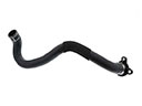
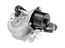
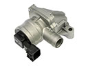
- Q: How to replace the auxiliary water pump on GMC Sierra 3500?A:Before changing the auxiliary water pump, drain the cooling system. Remove old 2 bolts and can (non-screw clamp bolts on inlet hose) from the front heater inlet hose . Next, connect the rear heater inlet hose clamp and disconnect the rear heater inlet hose, then reposition the rear heater inlet hose clamp . Unclip the heater outlet hose and remove electrical connection from the auxiliary water pump. Take out the nuts from the auxiliary water pump bracket and remove the auxiliary water pump from the vehicle. Remove the clips from the auxiliary water pump bracket then also the auxiliary water pump from the bracket. For installation, the auxiliary water Pump should be installed to the auxiliary water pump Bracket and clips should then be attached to the bracket. On the next step, install the auxiliary water pump back in the vehicle, with nuts to the auxiliary water pump bracket being secured to the nuts of 9 Nm (80 inch lbs.). The auxiliary water pump is connected to the electrical connector, install the heater outlet hose into the clip, and the rear heater inlet hose is installed into the auxiliary water pump. Set the rear heater inlet hose clamp and attach front heater inlet hose to auxiliary water pump and set the front heater inlet hose clamp. Finally, fill the cooling system.
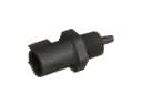
- Q: How to replace the Knock Sensor (KS) 1 on GMC Sierra 3500?A:To replace the Knock Sensor (KS) 1, drain the cooling system/engine block first. Remove the knock sensor electrical connector and knock sensor. For installation, apply the new knock sensor making sure the fastening of the new knock sensor is at 20 N.m (15lb ft) using Fastener Notice as per the place in the Service Precautions. Then, attach the knock sensor electrical connector and fill the cooling system/engine block.


