ChevyParts
My Garage
My Account
Cart
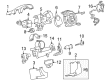
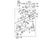
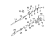
OEM Buick Steering Angle Sensor
Steering Column Angle Position Sensor- Select Vehicle by Model
- Select Vehicle by VIN
Select Vehicle by Model
orMake
Model
Year
Select Vehicle by VIN
For the most accurate results, select vehicle by your VIN (Vehicle Identification Number).
11 Steering Angle Sensors found


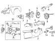
Buick Position Sensor Part Number: 13579486
$36.30 MSRP: $68.16You Save: $31.86 (47%)Ships in 1-2 Business DaysProduct Specifications- Other Name: Sensor, Steering Gear Hydraulic Valve; Steering Wheel Speed Sensor; Steering Angle Sensor; Angle Sensor
- Replaced by: 13587663


Buick Angle Sensor Part Number: 25849366
$49.84 MSRP: $96.72You Save: $46.88 (49%)Ships in 1-2 Business DaysProduct Specifications- Other Name: Sensor, Steering Gear Hydraulic Valve; Steering Wheel Speed Sensor; Steering Angle Sensor; Steering Sensor Assembly


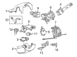
Buick Position Sensor Part Number: 84107026
$54.17 MSRP: $106.07You Save: $51.90 (49%)Product Specifications- Other Name: Sensor, Steering Gear Hydraulic Valve; Steering Wheel Speed Sensor; Steering Angle Sensor; Angle Sensor
- Replaces: 20795490


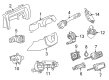
Buick Position Sensor Part Number: 13589991
$41.83 MSRP: $116.38You Save: $74.55 (65%)Ships in 1-2 Business DaysProduct Specifications- Other Name: Sensor, Steering Gear Hydraulic Valve; Steering Wheel Speed Sensor; Steering Angle Sensor; Angle Sensor; Steering Sensor Assembly
- Replaces: 13579709, 13589257, 13584209, 13513905


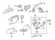
Buick Position Sensor Part Number: 13589398
$83.97 MSRP: $162.99You Save: $79.02 (49%)Ships in 1-2 Business DaysProduct Specifications- Other Name: Sensor, Steering Gear Hydraulic Valve; Steering Wheel Speed Sensor; Steering Angle Sensor; Angle Sensor; Steering Sensor Assembly


Buick Position Sensor Part Number: 25853012
Product Specifications- Other Name: Sensor, Steering Gear Hydraulic Valve; Steering Wheel Speed Sensor; Steering Angle Sensor; Angle Sensor


Buick Angle Sensor Part Number: 15115918
Product Specifications- Other Name: Sensor, Steering Gear Hydraulic Valve; Steering Wheel Speed Sensor; Steering Angle Sensor


Buick Angle Sensor Part Number: 13515749
Product Specifications- Other Name: Sensor Assembly, Steering Angle; Steering Wheel Speed Sensor; Steering Angle Sensor; Sensor, Steering Gear Hydraulic Valve
- Replaces: 13579487, 20962537


Buick Speed Sensor Part Number: 26064468
$72.07 MSRP: $128.70You Save: $56.63 (44%)Product Specifications- Other Name: Sensor, Steering Column; Steering Wheel Speed Sensor; Steering Angle Sensor; Position Sensor; Sensor


Buick Position Sensor Part Number: 15231652
$106.08 MSRP: $166.15You Save: $60.07 (37%)Product Specifications- Other Name: Sensor, Steering Column; Steering Wheel Speed Sensor; Steering Angle Sensor; Sensor
- Replaces: 26059045, 88965330
Buick Angle Sensor Part Number: 13587663
$38.17 MSRP: $68.16You Save: $29.99 (44%)Product Specifications- Other Name: Sensor, Steering Gear Hydraulic Valve; Steering Wheel Speed Sensor; Steering Angle Sensor
- Replaces: 13579486
Buick Steering Angle Sensor
Choose OEM Steering Angle Sensor, you're making the optimal decision for superior quality and perfect performance. You can feel confident because each component goes through stringent quality checks. Every part is carefully built to comply with Buick's factory specifications. You'll enjoy a smooth, worry-free installation that fits just right. At ChevyPartsGiant.com, you'll find it easy to get top-quality OEM Buick Steering Angle Sensor. You can shop at highly competitive prices and protect your budget. All our genuine Buick parts include a dependable manufacturer's warranty. You'll also appreciate our straightforward return policy and swift delivery services for extra convenience.
Buick Steering Angle Sensor Parts and Q&A
- Q: Does the steering angle sensor require centering after specific service procedures on Buick Enclave?A:The Steering Angle Sensor needs infrequent centering but recommends centering after these service procedures: steering gear replacement or Steering Column replacement or Steering Angle Sensor replacement or intermediate shaft replacement or electronic brake control module (EBCM) replacement or vehicle collisions or physical damage incidents. A scan tool allows you to perform the centering procedure which follows these specific steps: to begin the centering process select Steering Angle Sensor centering from the ebcm special functions list. Apply these steps: align front wheels forward with steering wheel and set the transmission to park position, perform the procedure with ignition switch on while engine remains off. Clear all existing dtcs previously set and follow the scan tool's procedures.
- Q: How to service the Steering Angle Sensor on Buick LeSabre?A:Start by determining the sensor type from available visuals before you begin sensor removal processes. Sensor connector placement begins from the right side marking the front position. The current sensor does not require centering operations prior to its removal for reuse. First disconnect the connector from the sensor and separate the sensor from its adapter and bearing assembly. Before sensor installation check that the sensor's front displays a foam ring together with a pin hole for centering alongside a flush rotor flange cuff. When reinstalling a reused sensor it's necessary to make an alignment mark on the rotor flange cuff prior to removal to prevent alignment issues. A fresh sensor delivery includes a built-in pin which must not be removed before installation. Keep the pin installed until you successfully position the sensor inside its mount. Put the sensor in alignment with the steering shaft before inserting it into the adapter and bearing assembly and attaching the sensor. A pin aperture on the sensor front surface resides together with a raised rotor flange cuff and an alignment reference point. The existing sensor requires its alignment marks on the raised rotor flange cuff to match before installing the sensor components. Each sensor requires the same alignment setup following installation including careful documentation of critical features and specific alignment points.


Related Buick Parts
 Buick Rack And Pinion
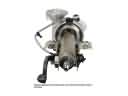 Buick Steering Column
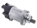 Buick Power Steering Assist Motor
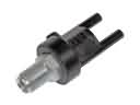 Buick Power Steering Control Valve
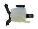 Buick Power Steering Reservoir
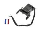 Buick Shift Interlock Solenoid
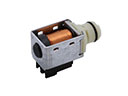 Buick Shift Solenoid
 Buick Steering Column Cover
 Buick Steering Column Seal
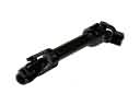 Buick Steering Shaft
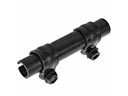 Buick Tie Rod Adjusting Sleeve
 Buick Tie Rod End