ChevyParts
My Garage
My Account
Cart
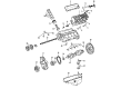
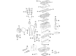
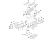
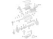
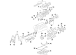
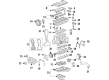
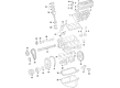
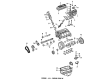
OEM Chevrolet Express 2500 Rocker Arm
Engine Rocker Arm- Select Vehicle by Model
- Select Vehicle by VIN
Select Vehicle by Model
orMake
Model
Year
Select Vehicle by VIN
For the most accurate results, select vehicle by your VIN (Vehicle Identification Number).
9 Rocker Arms found


Chevrolet Express 2500 Rocker Arms Part Number: 23500074
$19.84 MSRP: $32.68You Save: $12.84 (40%)Ships in 1-2 Business Days

Chevrolet Express 2500 Rocker Arms Part Number: 12619829
$15.74 MSRP: $25.93You Save: $10.19 (40%)Ships in 1-2 Business Days


Chevrolet Express 2500 Rocker Arms Part Number: 10214664
$14.44 MSRP: $23.79You Save: $9.35 (40%)Ships in 1-2 Business Days
Chevrolet Express 2500 Rocker Arms Part Number: 97365293
$80.98 MSRP: $162.59You Save: $81.61 (51%)Ships in 1-3 Business Days
Chevrolet Express 2500 Rocker Arms Part Number: 12696105
$13.64 MSRP: $22.47You Save: $8.83 (40%)Ships in 1-2 Business Days
Chevrolet Express 2500 Rocker Arms Part Number: 12625214
$37.35 MSRP: $58.51You Save: $21.16 (37%)Ships in 1-3 Business Days
Chevrolet Express 2500 Rocker Arms Part Number: 12599650
$57.50 MSRP: $90.07You Save: $32.57 (37%)Ships in 1-3 Business Days
Chevrolet Express 2500 Rocker Arms Part Number: 12522105

Chevrolet Express 2500 Rocker Arms Part Number: 98004537
$111.09 MSRP: $174.02You Save: $62.93 (37%)
Chevrolet Express 2500 Rocker Arm
Want to cut long-term maintenance and repair costs? Choose OEM Rocker Arm. Those parts deliver top durability you can trust. On our site, you'll find a huge catalog of genuine Chevrolet Express 2500 parts. Prices are unbeatable, so you can keep more in your pocket. Every OEM Chevrolet Express 2500 Rocker Arm includes a manufacturer's warranty. You can also get an easy return policy that keeps buying risk free. Fast delivery, get your car on the road quickly. It's simple to search, compare, and order. Stop guessing about quality or fit. Order today and save with parts that last.
Chevrolet Express 2500 Rocker Arm Parts Questions & Experts Answers
- Q: How to replace the valve rocker arm and push rods on Chevrolet Express 2500?A:Begin repairing the valve Rocker Arm and push rods by first reverting the valve Rocker Arm cover then note down and sort all parts for reconstruction purposes. The maintenance operation requires removal of valve rocker arms and their supports together with valve Pushrods. Check and assess the valve Rocker Arm as well as the valve Pushrod after cleaning them thoroughly. Follow this procedure when installing parts by maintaining their order and returning them to their default positions. The first step for valve Pushrod installation requires positioning the valve Rocker Arm support arrow in an upward direction before adding the valve Rocker Arm supports. His all parts with prelude gm p/n 12345501 or equivalent before installing them onto the contact surfaces that include the valve Pushrod socket , roller pivot , and valve stem tip . Begin by starting each valve Rocker Arm assembly bolt at position and before proceeding to the other bolt locations. The technician should rotate the crankshaft balancer until the crankshaft balancer alignment mark faces 57 to 63 degrees relative to the engine front cover alignment tab either clockwise or counter-clockwise. Valve Rocker Arm assemblies need no further adjustment after installation and correct torquing because the adjustment is already accomplished. Establish the valve Rocker Arm bolts at 30 nm (22 ft. Lbs.) torque along with the procedure of installing the valve Rocker Arm cover.

Related Chevrolet Express 2500 Parts
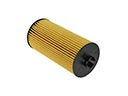 Chevrolet Express 2500 Oil Filter
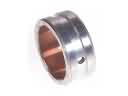 Chevrolet Express 2500 Balance Shaft Bearing Set
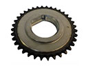 Chevrolet Express 2500 Balance Shaft Gear
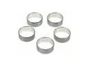 Chevrolet Express 2500 Camshaft Bearing
 Chevrolet Express 2500 Coolant Filter
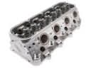 Chevrolet Express 2500 Cylinder Head
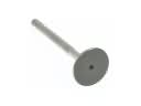 Chevrolet Express 2500 Exhaust Valve
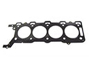 Chevrolet Express 2500 Head Gasket
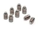 Chevrolet Express 2500 Lash Adjuster
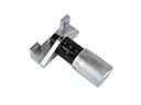 Chevrolet Express 2500 Timing Belt Tensioner
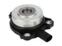 Chevrolet Express 2500 Variable Timing Adjuster Magnet
 Chevrolet Express 2500 Variable Timing Sprocket