
Popular OEM Chevrolet Express 2500 Parts
- Body & Hardware Parts View More >
- Steering Parts View More >
- Electrical Parts View More >
- Air & Fuel Delivery Parts View More >
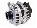
- Charging & Starting Parts View More >
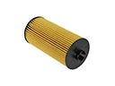
- Engine Parts View More >
- Belts & Cooling Parts View More >
- Suspension Parts View More >
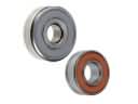
- Driveline & Axles Parts View More >
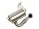
- Emission Control & Exhaust Parts View More >
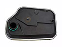
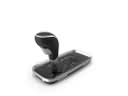
- Transmission Parts View More >
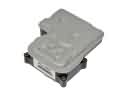
- Brakes Parts View More >

Why Buy Genuine Chevrolet Express 2500 Parts From ChevyPartsGiant.com
Looking for real Chevrolet Express 2500 parts? ChevyPartsGiant.com may be a better choice to find genuine parts at wallet-friendly prices. We sell only OEM Chevrolet Express 2500 parts, ensuring perfect fit, reliability, and long-term performance. With our website, you can easily get access to the same parts found at local Chevrolet stores. All components are produced by Chevrolet and are exclusively fitted on Chevrolet Express 2500 automobiles. By shopping at our store, you can enjoy the quality of the Chevrolet factory without the high prices of brick-and-mortar facilities. We achieve this because we are an online store operating at lower costs, which we pass on to you. We also have a user-friendly platform where you can find and order genuine Chevrolet Express 2500 parts swiftly. We are here to make your process of restoring a Chevrolet Express 2500 or dealing with simple repairs quick and inexpensive. We also make it easy to obtain Chevrolet Express 2500 parts at competitive shipping prices and a team of knowledgeable staff ready to take your order. Choose ChevyPartsGiant.com to save time and money, as well as keep your Chevrolet Express 2500 in the good condition.
The Chevrolet Express 2500 entered the market in 1996 to become one of the critical full-size vans with strengths in commercial transportation and passenger transport applications. The GMT600 platform used for Chevrolet Express 2500 construction is derives from the GMT400 architecture behind C/K fourth-generation trucks to build a durable box-type chassis that boosts its capacity to handle loads. The Express 2500 model introduced during 1996 supplied customers with choices between five engine models and the reliable 4L80E heavy-duty transmission that accommodated diverse operational needs. Driving performance and fuel efficiency saw improvements because the vehicle used the 6L90 six-speed automatic transmission until 2010. During the manufacturing period the Chevrolet Express 2500 received a major update in 2003 that combined new front-end designs and improved chassis parts for better aerodynamics and handling performance. The front axle advancement of 10 inches realigned the wheels toward safety zones. The Chevrolet Express 2500 serves 12 to 15 passengers through its functionality that suits both private and business transportation requirements. Factory specifications determine that Original Manufacturer parts guarantee both long-lasting service and dependable performance for your Chevrolet Express 2500.
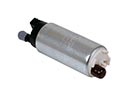
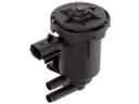
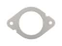
Chevrolet Express 2500 groups these concerns into fuel level sensing, engine sealing, and engine cooling. These issues share symptoms like poor drivability, rising temperatures, and inaccurate range estimates. In the fuel system, Express 2500 may show an erratic gauge and sudden low warnings. A worn sender inside the fuel pump module misreports volume and confuses trip planning. Replace the fuel pump on high mileage vehicles, confirm wiring integrity, and reset the cluster readings. For sealing, Express 2500 can leak coolant or oil at the intake manifold gasket. Internal leaks mix coolant with oil and risk bearing damage. Install a new intake manifold gasket, correct warped surfaces, and recheck for residue. For cooling, Express 2500 may lose coolant from a failing water pump and overheat. Install a new water pump, bleed the system, and verify cap and fan command. Pressure test, inspect hoses, and confirm thermostat opening meets Chevrolet service data. After repairs, road test the Chevrolet Express 2500 and monitor temperatures and fuel trims. Scan Chevrolet controllers, clear codes, and document baselines for future Chevrolet maintenance. This keeps the Express 2500 reliable in heavy traffic and hot weather.
Chevrolet Express 2500 Parts Questions & Answers
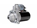
- Q: How to replace the alternator on Chevrolet Express 2500?A:Firstly separate the upper Fan Shroud before replacing the auxiliary generator. Start by removing the Drive Belt. Begin the process by disconnecting the auxiliary generator electrical connector followed by the positive cable procedure that includes boot slide-down and positive cable nut removal and cable removal sequence. You must first remove the auxiliary generator by removing all three mounting bolts. Position the new auxiliary generator into place before tightening the three bolts to 50 nm (37 lb ft) torque. Reconnect the positive cable by placing it correctly followed by tightening the positive cable nut to 10 nm (89 lb in). Replace the boot over the terminal stud afterward. Complete generator wiring after hooking up the electrical connector before fitting the Drive Belt and replacing the upper shroud.
- Q: How to replace the front side door emblem/nameplate on Chevrolet Express 2500?A:The first thing to do for replacing the front side door emblem/nameplate is to put tape around the space, making it easier to keep the emblem lined up. Set the heat gun (J 25070) 6.0 inches away from the surface and move it in circles around the emblem/nameplate for half a minute. Make sure to use a plastic, flat-bladed tool to remove the emblem/nameplate and keep the paint safe. Once you've removed the emblem/nameplate, go over the door panel surface and its back with 3M(TM) Scotch Brite Molding Adhesive Remover Disk (3M(TM) P/N If the emblem/nameplate location is not labeled, use tape to help you align it. Heat the door panel again using the heat gun (J 25070) until it's a minimum of 21°C (70°F), making sure the glue side of the emblem/nameplate stays cool. Take off the backing from the front end of the emblem/nameplate and stick it to the door panel surface as you keep taking off the rest of the backing. Hand roll the emblem/nameplate to ensure it sticks well and look at it to see if it is bonded before removing the tape from around the door emblem.
- Q: How to replace the distributor in an engine on Chevrolet Express 2500?A:Before changing the Distributor make sure to turn off the ignition, remove engine cover, air cleaner assembly and air intake resonator assembly. Compare the rotor's position with the cylinder it belongs to using the heater and the vacuum pipe connection. Disconnect the Spark Plug Wires from the Distributor Cap as follows: twist each wire boot 1/2 turn and simply pull on the boot. The electrical connection at the base of the Distributor is next to be pulled out, also, the 2 screws holding the Distributor Cap in place are to be removed and thrown away. Disconnect the Distributor Cap and use the grease pencil to mark the position of rotor with reference to the housing of Distributor and also the Intake Manifold of Distributor's. While you are pulling the Distributor out, observe that the rotor will rotate counter-clockwise about 42 degrees and put a mark number 2 on the base of the Distributor for realignment when installing. Your next step is to remove the mounting clamp hold-down bolt; pull out the Distributor. For installation procedure 1: using a new Distributor assembly, put 2 marks in the new housing at the same place as the original. Align rustor to the second mark , guide the Distributor on the engine, and bring the hole at hold down base on the engine cover hole at the Intake Manifold. As you install, the rotor will turn clockwise 42 degrees. Ensure the rotor segment is aligned with mark on the Distributor base. If there is a misalignment, remove and re-mount the Distributor. If you see any oil spill in the oil filler valve tube, feel free to replace that tube as well. Tighten the Distributor mounting clamp bolt to 25 n.m (18 lb ft) and fit the Distributor Cap while fitting the Distributor Cap screws that are new that need to be tightened to 2.4 n.m (21 lb in). Reconnect the electrical connector, reinstall the Spark Plug Wires and ignition coil wire making sure all are initially correct. Following the installation, if the malfunction indicator lamp lights up with a value of dtc p1345, the Distributor has been installed incorrectly. For installation method 2, turn the crankshaft balancer in a clockwise direction so that the alignment marks fall on the engine front cover tabs so that the number 1 Piston is at tdc of the compression stroke. Assemble the bottom stem of the Distributor with the white paint mark aligned with the pre-drilled indent hole in the gear with the make note of the rotor segment aligning as shown for a v6 engine. Using a long screwdriver, align the oil pump drive shaft with the Distributor's drive tab and guide the latter into the engine with the flat part in the direction of the car's front; the rotor segment must be aligned with the Distributor's pointer on the base of the latter. Make sure the Distributor mounting bolt is tightened to 25 n.m (18 lb ft) and fit the Distributor Cap then tighten new screws to 2.4 n.m (21 lb in), reconnect the electrical connector and plug in the spark plug and ignition coil wire making sure that it is in the correct orientation. Repeat installation procedure 2 should the malfunction indicator lamp light up following installation signifying a wrong installation. Finally, install the engine cover.
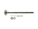
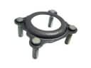
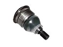
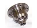
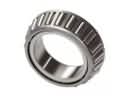
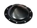
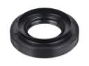
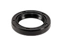
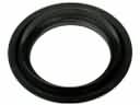
- Q: How to replace the Front Drive Axle Inner Wheel Seal and Inner Shaft Bearing on Chevrolet Express 2500?A:The first step to replace the Front Drive Axle Inner Shaft Seal and Inner Shaft Bearing requires lifting the vehicle while draining the differential carrier assembly fluid. The left side seal replacement requires disconnecting the wheel drive shaft from its inner shaft flange followed by taking off the inner shaft before removing the inner shaft seal cover bolts and assembly. The process to replace the left side bearing requires removal of the differential carrier assembly together with the left inner shaft and inner shaft seal cover bolts and assembly. Apply the J 29369-1 (Bushing and Bearing Remover) to the inner shaft bearing on its backside before connecting the J 2619-01 (Slide Hammer) for pulling out the inner shaft bearing. First remove the inner shaft from the housing after taking out the inner shaft and housing assembly to reach both the right side seal and bearing. Secure the inner shaft housing within a vise while applying the J 29369-1 (Bushing and Bearing Remover) to its back surface followed by attaching the J 2619-01 (Slide Hammer) to pull out the seal or seal along with bearing. Installation of right side bearings requires using the vise to secure the inner shaft housing prior to bearing installation through J 42211 (Axle Bearing Installer) and J 8092 (Universal Driver Handle - 3/4 in - 10). When installing the right side seal use J 42738 (Seal Installer) while carefully guiding the inner shaft through the oil seal. Put the inner shaft inside the housing before reuniting the components of the inner shaft and housing assembly. The owners must use J 42211 (Axle Bearing Installer) along with J 8092 (Universal Driver Handle - 3/4 in - 10) to install the left side bearing while they should also install the inner shaft seal cover assembly followed by securing the cover bolts at 18 Nm (13 lb ft) and guiding the left inner shaft through the oil seal until it contacts the differential case side gear. Use a soft-faced mallet while tapping the retaining ring into its groove until it reaches full seating then obstruct it with a finger to check its locking position. Reinstall the differential carrier assembly to the inner shaft flange as well as the wheel drive shaft and then add the suitable fluid to the differential carrier assembly before lowering the vehicle.


