ChevyParts
My Garage
My Account
Cart
OEM Chevrolet Express 3500 CV Boot
Axle Boot- Select Vehicle by Model
- Select Vehicle by VIN
Select Vehicle by Model
orMake
Model
Year
Select Vehicle by VIN
For the most accurate results, select vehicle by your VIN (Vehicle Identification Number).
2 CV Boots found

Chevrolet Express 3500 Outer Boot Part Number: 88982498

Chevrolet Express 3500 Inner Boot Part Number: 88982497
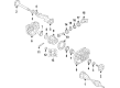
Chevrolet Express 3500 CV Boot
Want to cut long-term maintenance and repair costs? Choose OEM CV Boot. Those parts deliver top durability you can trust. On our site, you'll find a huge catalog of genuine Chevrolet Express 3500 parts. Prices are unbeatable, so you can keep more in your pocket. Every OEM Chevrolet Express 3500 CV Boot includes a manufacturer's warranty. You can also get an easy return policy that keeps buying risk free. Fast delivery, get your car on the road quickly. It's simple to search, compare, and order. Stop guessing about quality or fit. Order today and save with parts that last.
Chevrolet Express 3500 CV Boot Parts and Q&A
- Q: How to replace the outer CV Boot and CV Joint on Chevrolet Express 3500?A:The first step to replace a wheel drive shaft outer joint and boot requires removal of the wheel drive shaft. Set the Axle Shaft on a bench vise with a shop towel protecting it. Position the wheel drive shaft horizontally. Use a side cutter or alternate tool to eliminate and dispose of the large seal clamp followed by removing and discarding the small seal clamp. Set the seal apart from the joint's outer race at the large end before placing it behind the joint surface. To extract the wheel drive shaft outer joint from the Axle Shaft bar, an assistant will support the joint housing while placing a wood block under the seal to strike with a hammer against the wood block until the Axle Shaft retaining ring compresses enough to free the joint. You need to keep hammering the wood block until you remove the outer joint. Extract both the retaining ring and the seal from the wheel drive shaft bar. Install the large clamp alongside the small clamp on the seal before mounting the seal onto the wheel drive shaft bar followed by the retaining ring. Add service kit grease to the outer joint before setting it horizontally while you join its inner race splines to the Axle Shaft splines. Use a flat-bladed screwdriver to depress the retaining ring into the wheel drive shaft bar groove while you push the outer joint onto the Axle Shaft. Continuously move the tool around the ring until it achieves the desired compression. Use a wood block to cover the outer joint's threaded shaft end then hit it with a hammer until complete seating occurs on the wheel drive shaft bar. Secure the Axle Shaft so its inner race stepped surfaces entirely seat before placing the small end of the seal over its corresponding wheel shaft bar groove. Use clamp pliers (J 43218) to compress the small clamp until dimension (A) reaches the size range of 0.5-1.6 mm (0.02-0.06 in). After venting the joint to remove excess air, tighten the larger clamp with clamp pliers (J 43218) until dimension (A) reaches the range of 0.5-1.6 mm (0.02-0.06 in). The wheel drive shaft should be installed after completion.
- Q: How to service and repair the CV Boot and CV Joint on Chevrolet Express 3500?A:Begin constant velocity joint boot maintenance and repair by removing the wheel drive shaft through correct procedures. Set the wheel drive shaft on top of a bench vise then cover its Axle Shaft with a shop towel. Use side cutters to remove the large seal clamp and small seal clamp then throw away these clamps. Move the seal behind the joint face by separating it from the joint outer race at the large end. Use an assistant to maintain the joint housing while an operator removes the outer joint from the wheel drive shaft bar after cleaning grease from the joint inner race cage and balls. First place a wood block between the seal and joint face at the joint area before hitting the block with a hammer to compress the Axle Shaft retaining ring until the outer joint detaches. The maintenance process requires wheel drive shaft bar operators to first remove both the retaining ring and seal. Begin installation by placing the large clamp and the small clamp on the seal before placing the seal onto the wheel drive shaft bar and adding the retaining ring. After using service kit grease to fill the outer joint you should position it at a horizontal angle while connecting inner race splines to Axle Shaft splines. Compress the Axle Shaft retaining ring using a flat-bladed screwdriver or equivalent tool to push the ring groove into the wheel drive shaft's open end while you fully press the outer joint onto the Axle Shaft. Work your way around the retaining ring until it becomes fully compressed. Use a wood block to protect the outer joint threaded shaft end while you hammer it until complete onto the wheel drive shaft bar. The mating groove in the wheel drive shaft bar must receive the small end of the seal before aligning the stepped surfaces of the Axle Shaft with its inner race. Begin by applying clamp pliers (J 43218) to compress the small clamp. Maintain compression until dimension (A) reaches 0.5-1.6 mm (0.02-0.06 in). After venting the joint, finish by securing the large clamp using clamp pliers (J 43218) until dimension (A) stands at 0.5-1.6 mm (0.02-0.06 in). Programming of the wheel drive shaft must be the final stage of the installation process.


Related Chevrolet Express 3500 Parts
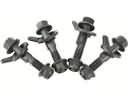 Chevrolet Express 3500 Alignment Bolt
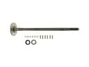 Chevrolet Express 3500 Axle Shaft
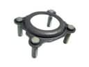 Chevrolet Express 3500 Axle Shaft Retainer
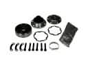 Chevrolet Express 3500 CV Joint
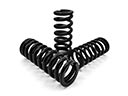 Chevrolet Express 3500 Coil Springs
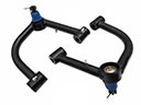 Chevrolet Express 3500 Control Arm
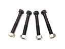 Chevrolet Express 3500 Control Arm Bolt
 Chevrolet Express 3500 Drive Shaft
 Chevrolet Express 3500 Shock Absorber
 Chevrolet Express 3500 Spare Wheel
 Chevrolet Express 3500 Torsion Bar
 Chevrolet Express 3500 Wheel Cover