ChevyParts
My Garage
My Account
Cart
OEM Chevrolet Lumina Steering Knuckle
Front Steering Knuckle- Select Vehicle by Model
- Select Vehicle by VIN
Select Vehicle by Model
orMake
Model
Year
Select Vehicle by VIN
For the most accurate results, select vehicle by your VIN (Vehicle Identification Number).
13 Steering Knuckles found


Chevrolet Lumina Strut Part Number: 89047630


Chevrolet Lumina Strut Part Number: 89047629
Chevrolet Lumina Strut Part Number: 89047631
Chevrolet Lumina Strut Part Number: 89047626
Chevrolet Lumina Strut, Passenger Side Part Number: 22064118

Chevrolet Lumina Knuckle Part Number: 10056762
Chevrolet Lumina Strut Part Number: 89047628

Chevrolet Lumina Knuckle, Rear Driver Side Part Number: 18060598

Chevrolet Lumina Knuckle, Rear Passenger Side Part Number: 18060244
Chevrolet Lumina Knuckle, Rear Passenger Side Part Number: 18023002
Chevrolet Lumina Knuckle, Rear Driver Side Part Number: 18023001
Chevrolet Lumina Knuckle, Rear Passenger Side Part Number: 18020443
Chevrolet Lumina Knuckle, Rear Driver Side Part Number: 18020442
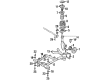
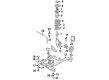
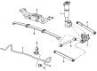
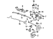
Chevrolet Lumina Steering Knuckle
Want to cut long-term maintenance and repair costs? Choose OEM Steering Knuckle. Those parts deliver top durability you can trust. On our site, you'll find a huge catalog of genuine Chevrolet Lumina parts. Prices are unbeatable, so you can keep more in your pocket. Every OEM Chevrolet Lumina Steering Knuckle includes a manufacturer's warranty. You can also get an easy return policy that keeps buying risk free. Fast delivery, get your car on the road quickly. It's simple to search, compare, and order. Stop guessing about quality or fit. Order today and save with parts that last.
Steering Knuckle is a part that represents high quality and flawless work in Chevrolet Lumina models line-up manufactured from 1989 to 2013. Being an intermediate assembly between the suspension and steering systems, Chevrolet Lumina steering knuckle helps the front wheels translate between vertical and horizontal motions according to the road surface irregularities encountered. This component can be installed on many Lumina models, both the RWD and FWD, AWD, and 4WD, so it proves to be quite versatile. Steering Knuckle has superior designs, moving from the kingpin designs to ball joint kinematics, thus increasing the knuckle's resilience. Steering Knuckle should be inspected periodically to enhance the strength of the vehicle, and more so after suspension work to enhance safety. The Steering Knuckle cannot just be considered as an ordinary car component since it performs a vital function of enabling efficient and safe handling of a car. Further, Steering Knuckle has the provision for the affixation of control arms and tie-rod ends, which enhances the vehicle's dynamism. In the Steering Knuckle, strong architecture, alongside the new recreational incorporation of the Lumina has indeed placed this brand in an advantageous position in the cars market, which reaffirms Chevrolet Lumina as a reliable midsize car that has undergone transformation with the new inventions in technology as well as safety measures.
Chevrolet Lumina Steering Knuckle Parts and Q&A
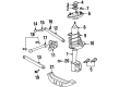
- Q: How to service and repair the steering knuckle on Chevrolet Lumina?A:In order to service and repair the Steering Knuckle, use the j 35917 Tie Rod puller/Ball Joint remover to remove the outer tie rods from the steering knuckles after scribing the strut mount cover for installation purposes and removing the three strut mount cover nuts. Lift and adequately raise the vehicle and after that, remove the tire and wheel and then followed by the brake caliper and mounting bracket and brake rotor. Unplug the abs wheel speeds sensor, and force the drive axle through the Wheel Hub/bearing splines. Unbolt the two Wheel Hub and bearing to knuckle attaching bolts and remove the Ball Joint heat shield by unbolt its retaining bolts. Using a wrong tool to separate the Ball Joint from the knuckle can cause a lot of damage. Thus, using the wrong tool is of the utmost importance. Next, the lower Ball Joint to knuckle attaching nut to be taken off and the j 35917 to be used to decompose the ball to the lower Control Arm. Remove the knuckle/strut from the vehicle when taking out the three strut mount cover nuts. For start of installation, install the strut mount cover and upper strut mount to body attaching nuts while not tightening them until the vehicle is lowered to the floor. Mount the Ball Joint heat shield with its attaching bolts and tighten them to 7 nm (62 inch lbs.). Move on to install the lower Ball Joint to the Control Arm, and then Tie Rod to knuckle attaching nut. Gently guide the drive axle into the knuckle hole and install the two hub and bearing-to-knuckle attachment bolts. Retie the abs wheel speed sensor and install the brake rotor, brake caliper, and mounting bracket. Lastly, put in the tire and wheel, lower the vehicle and align the scribe marks followed, and tighten the nuts of the strut mount cover to 33 nm (24 ft. Lbs.).

Related Chevrolet Lumina Parts
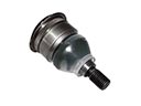 Chevrolet Lumina Ball Joint
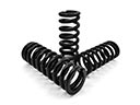 Chevrolet Lumina Coil Springs
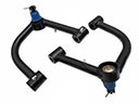 Chevrolet Lumina Control Arm
 Chevrolet Lumina Control Arm Bolt
 Chevrolet Lumina Control Arm Bracket
 Chevrolet Lumina Crossmember Bushing
 Chevrolet Lumina Leaf Spring Plate
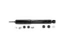 Chevrolet Lumina Shock Absorber
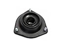 Chevrolet Lumina Shock And Strut Mount
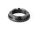 Chevrolet Lumina Spindle Nut
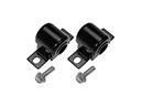 Chevrolet Lumina Sway Bar Bushing
 Chevrolet Lumina Sway Bar Link