
Popular OEM Chevrolet Lumina Parts
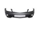
- Body & Hardware Parts View More >
- Steering Parts View More >
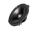
- Electrical Parts View More >
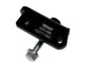
- Air & Fuel Delivery Parts View More >
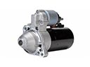
- Charging & Starting Parts View More >
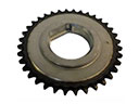
- Engine Parts View More >
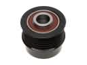
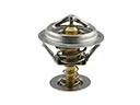
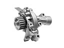
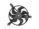
- Belts & Cooling Parts View More >
- Suspension Parts View More >
- Emission Control & Exhaust Parts View More >
- Transmission Parts View More >
- Brakes Parts View More >
- Headlights & Lighting Parts View More >

Why Buy Genuine Chevrolet Lumina Parts From ChevyPartsGiant.com
Looking for real Chevrolet Lumina parts? ChevyPartsGiant.com may be a better choice to find genuine parts at wallet-friendly prices. We sell only OEM Chevrolet Lumina parts, ensuring perfect fit, reliability, and long-term performance. With our website, you can easily get access to the same parts found at local Chevrolet stores. All components are produced by Chevrolet and are exclusively fitted on Chevrolet Lumina automobiles. By shopping at our store, you can enjoy the quality of the Chevrolet factory without the high prices of brick-and-mortar facilities. We achieve this because we are an online store operating at lower costs, which we pass on to you. We also have a user-friendly platform where you can find and order genuine Chevrolet Lumina parts swiftly. We are here to make your process of restoring a Chevrolet Lumina or dealing with simple repairs quick and inexpensive. We also make it easy to obtain Chevrolet Lumina parts at competitive shipping prices and a team of knowledgeable staff ready to take your order. Choose ChevyPartsGiant.com to save time and money, as well as keep your Chevrolet Lumina in the good condition.
For fifteen years General Motors manufactured Chevrolet Lumina vehicles under the brand through five evolutionary stages of automotive engineering. The Chevrolet Lumina launched with V6 engine options that included a 3.1L V6 together with a 3.4L DOHC V6 which specifically powered the sporty Z34 variant. During the second-generation Lumina production period from 1995 to 2001 engineers introduced two new V6 engine options which included the 3.1L and 3.8L (3800 Series II) for market availability. All trim levels on the third and fourth generations of Lumina received V8 power units together with a 2.5L LB8 V6 engine version introduced for the Philippine market between 2005 and 2006. The Chevrolet Lumina models came with three different transmission options: the first generation offered a 4-speed automatic and a 5-speed manual coupling with a 3-speed automatic in its lineup and the second generation exclusively used two 4-speed automatic transmissions. The original Lumina was built on GM's W-body platform. Later international versions, particularly those based on the Holden Commodore, used the GM Zeta platform. From 1995 onwards the Chevrolet Lumina introduced airbags to its array of options which also included a 107.5-inch wheelbase and different trim levels. Our online shop provides authentic Chevrolet parts which enable owners of Chevrolet Lumina to perform high-quality maintenance and repair work.
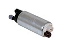
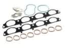
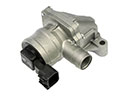
Chevrolet Lumina indicates grouped complaints over the issues with the engine sealing, fuel delivery, and the steering hydraulics. In the engine management, the Lumina may start developing leaks that will lead to deterioration in lubrications and coolant. A compromised intake manifold gasket will permit coolant or oil to leak or combine, both of which are harmful to bearings. Install and then reassemble the intake manifold gasket, cleaning up mating surfaces and tightening assembly fasteners in order. Check the lube oil quality, the coolant quantity, and the quality of idling on the Lumina after a service. In fuel delivery, the Lumina will stall or not restart after heat soak. A weak fuel pump decreases pressure, resulting in delay and long cranking. Install a quality fuel pump, check voltage and grounds, and check pressure with a gauge. Insert review trim, bleed air lines and re-test the Chevrolet Lumina on the road. In steering hydraulics, the Lumina has the tendency to leak fluid and lose its assist when in park. A damaged high-pressure power steering hose will spray fluid on hot items and make it tough to control. Check the pump output and tension of the belt, replace the power steering hose and rubber, proper secured routing. Disconnect the line, drain off fluid, and bleed air, and ascertain the silent operation of Chevrolet. On cross systems, early checks and documentation are supported on the Chevrolet Lumina.
Chevrolet Lumina Parts Questions & Answers
- Q: How to Service and Repair the Intake Manifold on a Chevrolet Lumina?A: You must start by disconnecting the battery ground cable to replace a lower Intake Manifold. Start by removing the upper Intake Manifold before disconnecting the radiator inlet hose along with the Thermostat bypass hose and completing the removal of the Thermostat bypass pipe. The work sequence requires removal of three parts: the left valve Rocker Arm cover and generator and the right valve Rocker Arm cover. Begin by disconnecting the engine coolant temperature (ECT) wiring harness and removing the Fuel Injector and manifold air pressure (MAP) wiring harness. Next detach the fuel pipe clip bolt and its retaining clip. Begin by removing the fuel feed and return pipes that attach to the Fuel Injector rail before taking the Fuel Injector rail off. Move the Power Steering Pump to a suitable location before disconnecting the heater inlet pipe connected to the lower Intake Manifold through a heater hose. The procedure requires removal of the lower Intake Manifold bolts followed by the lower Intake Manifold and valve rocker arms and push rods. The technician cleans all seal and gasket areas on both the engine block and cylinder heads before removing residual rtv sealer. When installing a new lower Intake Manifold begin by taking off the ect sensor and water outlet bolts before removing the water outlet. The water outlet must be bolted down with 25 nm (18 ft. Lbs.) torque during installation if you take off the Thermostat or water outlet. Reinstall the ect sensor when it has been removed. Place an 8-12 mm bead of rtv sealer (GM P/N 12345739 or equivalent) on the lower Intake Manifold contact ridges between the engine block then install lower Intake Manifold gaskets followed by push rods and valve rocker arms. Apply gm p/n 12345382 sealant to all lower Intake Manifold bolt threads and tighten the vertical and diagonal bolts to 13 nm (115 inch lbs.) apply a torque of 13 nm (115 inch lbs.) when tightening the diagonal bolts. Hand tighten the vertical and diagonal lower Intake Manifold bolts, then tighten the vertical bolts to 13 nm (115 inch lbs.) and the diagonal bolts to 13 nm (115 inch lbs.). First install both the Power Steering Pump and the heater inlet pipe with its attached heater hose before reattaching the Fuel Injector rail. Position the fuel return and feed pipes onto the Fuel Injector rail while securing the fuel pipe clip with a torque of 8 nm (71 inch lbs.). Begin by connecting the Thermostat bypass hose and radiator inlet hose followed by installing the Fuel Injector and map wiring harness and the ect wiring harness. As a conclusion reinstall the right and left valve Rocker Arm covers with the generator and upper Intake Manifold followed by reconnecting the battery ground cable.
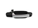
- Q: How to replace the rear side outer door handle on Chevrolet Lumina?A: Start the rear side door outside handle replacement by removing both trim panel and water deflector. Use side cutters to sever the outside handle rod-to-lock clip from the lock before you unscrew the remaining part of the clip from the rod and dispose of it. Remove the two rivets securing the outside door handle by drilling and take out the parts from the rod and door. Once installed you should first attach the outside door handle rod to the door handle followed by installing the handle together with the rod to the door. Take rivets to secure the handle then add a new outside handle rod-to-lock clip onto the door lock lever and position the rod inside the clip to prevent free movement. The installation ends with placement of the water deflector along with the trim panel while the threaded outside door handle rod passes beneath the clip cover.
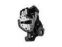
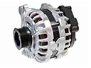
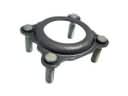
- Q: How to Service and Repair an Alternator for Rear on Chevrolet Lumina?A: Start by removing the generator rear brace stud from the generator then remove the generator rear brace nut from the engine stud on the engine Intake Manifold and finally detach the generator rear brace. First secure the generator rear brace to both generator and engine Intake Manifold engine stud before loosely attaching the generator rear brace stud to the generator body. Install the generator rear brace nut onto the engine stud on the Intake Manifold with a torque action of 25 n.m (18 lb ft) followed by generator rear brace study torque at 25 n.m (18 lb ft).
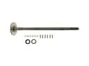
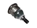
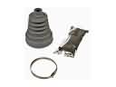
- Q: How to replace the left front wheel drive shaft wheel seal on Chevrolet Lumina?A: Start the procedure for left front wheel drive shaft oil seal replacement by adequately supporting the vehicle through proper vehicle lifting. Start replacement by removing both the left front tire and wheel and then the left engine splash shield. Detach the stabilizer shaft brackets from the left lower Control Arm before you remove both Tie Rod End from the left Steering Knuckle and the left lower Ball Joint from the left lower Control Arm. The left drive axle requires disconnection from the transaxle before securing it to the left Steering Knuckle and strut. A suitable tool such as a screwdriver should be used to remove seal (409) from its bore while protecting the bore's surface. Apply transaxle fluid on the seal lip before inserting a new seal (409) using the left side axle seal installer (J34115) along with the axle seal protector (J37292-B) inside it. While inserting the Axle Shaft ensure it passes by the lip seal without the splines touching the lip surface to avoid seal damage. After reattaching the drive axle connect to the transaxle operator should remove the axle seal protector (J37292-B) to start left lower Ball Joint installation onto the left Control Arm and then left Tie Rod End installation onto the left wheel knuckle followed by the left stabilizer shaft bracket installation onto the left Control Arm. Put back the left engine splash shield followed by installing the left front tire and wheel. Then lower the vehicle. Another requirement entails checking the fluid level to the specified amount while inspecting that the repair work was correctly finalized without leaks.


