ChevyParts
My Garage
My Account
Cart
OEM Chevrolet Silverado 3500 Classic Fuel Rail
Engine Fuel Rail- Select Vehicle by Model
- Select Vehicle by VIN
Select Vehicle by Model
orMake
Model
Year
Select Vehicle by VIN
For the most accurate results, select vehicle by your VIN (Vehicle Identification Number).
6 Fuel Rails found


Chevrolet Silverado 3500 Classic Fuel Rail Part Number: 97361352
$351.85 MSRP: $714.61You Save: $362.76 (51%)

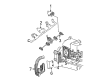
Chevrolet Silverado 3500 Classic Fuel Rail Part Number: 97361353
$336.68 MSRP: $683.83You Save: $347.15 (51%)


Chevrolet Silverado 3500 Classic Fuel Rail Part Number: 17113695
$104.95 MSRP: $327.45You Save: $222.50 (68%)Ships in 1-2 Business Days


Chevrolet Silverado 3500 Classic Fuel Rail Part Number: 12602113
$114.68 MSRP: $232.93You Save: $118.25 (51%)Ships in 1-2 Business Days
Chevrolet Silverado 3500 Classic Fuel Rail Part Number: 12599737

Chevrolet Silverado 3500 Classic Fuel Rail Part Number: 12574941
Chevrolet Silverado 3500 Classic Fuel Rail
Want to cut long-term maintenance and repair costs? Choose OEM Fuel Rail. Those parts deliver top durability you can trust. On our site, you'll find a huge catalog of genuine Chevrolet Silverado 3500 Classic parts. Prices are unbeatable, so you can keep more in your pocket. Every OEM Chevrolet Silverado 3500 Classic Fuel Rail includes a manufacturer's warranty. You can also get an easy return policy that keeps buying risk free. Fast delivery, get your car on the road quickly. It's simple to search, compare, and order. Stop guessing about quality or fit. Order today and save with parts that last.
Chevrolet Silverado 3500 Classic Fuel Rail Parts and Q&A
- Q: How to replace the Fuel Injection Fuel Rail Assembly on Chevrolet Silverado 3500 Classic?A:The first task for Fuel Rail assembly replacement involves relieving fuel system pressure through the use of ch 48027 or without tool usage. Start by untightening the wire harness bracket nut then disconnect the evap purge solenoid electrical connector along with the generator electrical connector and manifold absolute pressure (MAP) sensor and Knock Sensor. You must first disconnect the electronic throttle control (ETC) electrical connector by removing its gray retainer then pushing down the black clip before separating the connector. Begin by taking out the cpa retainer from the connector position assurance on both right and left side engine areas before disconnecting the main coils and Fuel Injectors on their respective sides. Uninstall the harness clips from the Fuel Rail while setting the engine wire harness to one side. First mark the Fuel Injector electrical connectors for assembly then pull the cpa retainer up one click while pushing the tab in and disconnect each Fuel Injector electrical connector. Before extracting the Fuel Rail bolts one must detach both the positive crankcase ventilation (PCV) hose and fuel feed pipe from the Fuel Rail. You should carefully take out the Fuel Rail while maintaining the injector electrical connector terminals and spray tips intact before using caps to block off the fittings and prevent contaminants. Use a spray type engine cleaner to clean the Fuel Rail before removing the Fuel Rail with each Fuel Injector containing a new low end o-ring seal that needs discarding. Before Fuel Injector lower o-ring seal installation attention should be given to lubricating them with clean engine oil. Copper threadocker gm p/n 12345382 (Canadian P/N 10953489) needs application on each Fuel Rail bolt threads before bolting and tightening to 10 n.m (89 lb in) torque. The correct reassembly method requires installation of Fuel Injector electrical connectors to matching injectors followed by pushing the cpa retainer for one click per connector. The engine wire harness must be positioned while you connect main coil along with fuel injectors on the left side before installing harness clips onto the Fuel Rail and cpa retainer. Next mount the cpa retainer before attaching the harness clips to the Fuel Rail of the right side. Start with the gray retainer connection of the etc electrical connector before proceeding to connect the MAP Sensor and Knock Sensor then moving to the Intake Manifold for the Knock Sensor harness connector and evap purge solenoid electrical connector and generator electrical connector. To complete the installation process install the wire harness bracket nut and tighten it to 5 n.m (44 lb in) while also tightening the fuel fill cap and connecting the negative Battery Cable and inspect for leaks by starting the ignition for 2 seconds and waiting 10 seconds before a second ignition start-up to check for fuel leaks.

Related Chevrolet Silverado 3500 Classic Parts
 Chevrolet Silverado 3500 Classic Air Filter
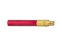 Chevrolet Silverado 3500 Classic Air Hose
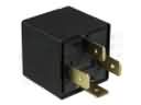 Chevrolet Silverado 3500 Classic Daytime Running Light Relay
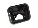 Chevrolet Silverado 3500 Classic Fuel Filler Housing
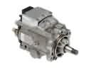 Chevrolet Silverado 3500 Classic Fuel Injection Pump
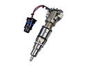 Chevrolet Silverado 3500 Classic Fuel Injector
 Chevrolet Silverado 3500 Classic Fuel Injector O-Ring
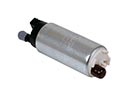 Chevrolet Silverado 3500 Classic Fuel Pump
 Chevrolet Silverado 3500 Classic Gas Cap
 Chevrolet Silverado 3500 Classic Intake Manifold Gasket
 Chevrolet Silverado 3500 Classic Mass Air Flow Sensor
 Chevrolet Silverado 3500 Classic Throttle Body