ChevyParts
My Garage
My Account
Cart
OEM Chevrolet Silverado 3500 Fuel Rail
Engine Fuel Rail- Select Vehicle by Model
- Select Vehicle by VIN
Select Vehicle by Model
orMake
Model
Year
Select Vehicle by VIN
For the most accurate results, select vehicle by your VIN (Vehicle Identification Number).
10 Fuel Rails found


Chevrolet Silverado 3500 Fuel Rail Part Number: 97361352
$351.85 MSRP: $714.61You Save: $362.76 (51%)

Chevrolet Silverado 3500 Fuel Rail Part Number: 97361353
$336.68 MSRP: $683.83You Save: $347.15 (51%)


Chevrolet Silverado 3500 Fuel Rail Part Number: 17113695
$104.95 MSRP: $327.45You Save: $222.50 (68%)Ships in 1-2 Business Days


Chevrolet Silverado 3500 Fuel Rail Part Number: 12602113
$114.68 MSRP: $232.93You Save: $118.25 (51%)Ships in 1-2 Business Days

Chevrolet Silverado 3500 Fuel Rail Part Number: 97303659


Chevrolet Silverado 3500 Fuel Rail Part Number: 97208075


Chevrolet Silverado 3500 Fuel Rail Part Number: 17113696


Chevrolet Silverado 3500 Fuel Rail Part Number: 12575055

Chevrolet Silverado 3500 Fuel Rail Part Number: 97303658

Chevrolet Silverado 3500 Fuel Rail Part Number: 12574941
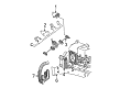
Chevrolet Silverado 3500 Fuel Rail
Want to cut long-term maintenance and repair costs? Choose OEM Fuel Rail. Those parts deliver top durability you can trust. On our site, you'll find a huge catalog of genuine Chevrolet Silverado 3500 parts. Prices are unbeatable, so you can keep more in your pocket. Every OEM Chevrolet Silverado 3500 Fuel Rail includes a manufacturer's warranty. You can also get an easy return policy that keeps buying risk free. Fast delivery, get your car on the road quickly. It's simple to search, compare, and order. Stop guessing about quality or fit. Order today and save with parts that last.
Chevrolet Silverado 3500 Fuel Rail Parts and Q&A
- Q: How to replace the fuel rail assembly on Chevrolet Silverado 3500?A:Before replacing the Fuel Rail assembly it is vital to reduce pressure in the fuel system. Start by first removing the bracket nut securing the wire harness and then unplug the evaporative emission (EVAP) purge solenoid electrical connector combined with the generator electrical connector and the manifold absolute pressure (MAP) sensor and Knock Sensor. The first step is to detach the Intake Manifold's Knock Sensor harness connector followed by removing the electronic throttle control (ETC) electrical connector through releasing its gray retainer and pressing down the black clip before unconnecting the connector. The procedure starts by removing the connector position assurance (CPA) retainer from the right-side engine area followed by disconnecting the main coil and Fuel Injectors from their mounting positions along the right engine side. Afterward the Fuel Rail harness clips need to be removed from the coil. First detach the Fuel Injector and main coil connectors from the left engine side where the cpa retainer existed before removing all harness clips from the Fuel Rail. After placing the engine wire harness to the side you should mark the Fuel Injector electrical connectors so their order is correct for reassembly. Perform the following steps for each Fuel Injector electrical connector by pushing up the cpa retainer 1 click then pushing the tab into place and removing the electrical connector. The positive crankcase ventilation (PCV) hose must be detached while removing the fuel feed pipe that connects to the Fuel Rail. Extract the Fuel Rail by removing its bolts with caution because this process may damage injector electrical connector terminals and prevent contamination through the fittings so protect them with caps. Activate a spray type engine cleaner on the Fuel Rail for cleaning only but never saturate the rail with liquid cleaning solvent. Each injector needs its Fuel Injector lower o-ring seal to be removed before discarding. Before installing the fuel injectors users must apply engine oil to new lower o-ring seals and position them at each injector. Apply a 5 mm threadlock band of gm p/n 12345382 (Canadian P/N 10953489) to the Fuel Rail bolts before tightening them to 10 n.m using a 89 lb in torque value. Final steps include linking the fuel feed pipe to the Fuel Rail as well as mounting the pcv hose followed by connecting the Fuel Injector electrical connectors. Secure correct reassembly through appropriate placement of connectors onto their designated injectors while settling the cpa retainer into 1 click per element. The engine wire harness must be positioned and the main coil and fuel injectors connected on the left side before attaching harness clips to both the Fuel Rail and the cpa retainer. The right side main coil and fuel injectors need attachment while also installing the cpa retainer and the harness clips to the Fuel Rail . First complete etc electrical connector connection by using the gray retainer followed by hookup of the MAP Sensor and Knock Sensor before mounting the Knock Sensor harness connector on the Intake Manifold and installing evap purge solenoid electrical connector and generator electrical connector. To finish the installation you should install the wire harness bracket nut while tightening it to 5 n.m (44 lb in) and complete the installation with tightening the fuel fill cap and negative Battery Cable connection before checking for leaks through a three-step ignition test.

Related Chevrolet Silverado 3500 Parts
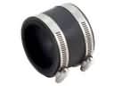 Chevrolet Silverado 3500 Air Intake Coupling
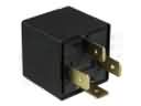 Chevrolet Silverado 3500 Daytime Running Light Relay
 Chevrolet Silverado 3500 Exhaust Flange Gasket
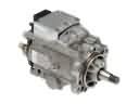 Chevrolet Silverado 3500 Fuel Injection Pump
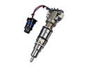 Chevrolet Silverado 3500 Fuel Injector
 Chevrolet Silverado 3500 Fuel Injector O-Ring
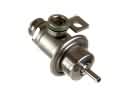 Chevrolet Silverado 3500 Fuel Pressure Regulator
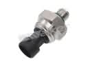 Chevrolet Silverado 3500 Fuel Pressure Sensor
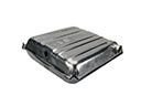 Chevrolet Silverado 3500 Fuel Tank
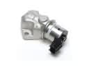 Chevrolet Silverado 3500 Idle Control Valve
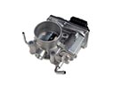 Chevrolet Silverado 3500 Throttle Body
 Chevrolet Silverado 3500 Throttle Cable