ChevyParts
My Garage
My Account
Cart
OEM Chevrolet Suburban 2500 Fuel Rail
Engine Fuel Rail- Select Vehicle by Model
- Select Vehicle by VIN
Select Vehicle by Model
orMake
Model
Year
Select Vehicle by VIN
For the most accurate results, select vehicle by your VIN (Vehicle Identification Number).
26 Fuel Rails found


Chevrolet Suburban 2500 Fuel Rail Part Number: 17113695
$104.95 MSRP: $327.45You Save: $222.50 (68%)Ships in 1-2 Business Days

Chevrolet Suburban 2500 Fuel Rail Part Number: 97361353
$336.68 MSRP: $683.83You Save: $347.15 (51%)


Chevrolet Suburban 2500 Fuel Rail Part Number: 12602113
$114.68 MSRP: $232.93You Save: $118.25 (51%)Ships in 1-2 Business Days


Chevrolet Suburban 2500 Fuel Rail Part Number: 97361352
$351.85 MSRP: $714.61You Save: $362.76 (51%)
Chevrolet Suburban 2500 Fuel Rail Part Number: 12621668
$198.77 MSRP: $359.76You Save: $160.99 (45%)Ships in 1-2 Business Days
Chevrolet Suburban 2500 Fuel Rail Part Number: 12621663
$236.37 MSRP: $427.82You Save: $191.45 (45%)Ships in 1-2 Business DaysChevrolet Suburban 2500 Fuel Rail Part Number: 12621665
$184.53 MSRP: $374.78You Save: $190.25 (51%)Ships in 1-2 Business DaysChevrolet Suburban 2500 Fuel Rail Part Number: 89018110
$188.56 MSRP: $341.28You Save: $152.72 (45%)Ships in 1-2 Business Days

Chevrolet Suburban 2500 Fuel Rail Part Number: 97303659


Chevrolet Suburban 2500 Fuel Rail Part Number: 97208075


Chevrolet Suburban 2500 Fuel Rail Part Number: 17113696


Chevrolet Suburban 2500 Fuel Rail Part Number: 12575055
Chevrolet Suburban 2500 Fuel Rail Part Number: 12592185
Chevrolet Suburban 2500 Fuel Rail Part Number: 12592182
Chevrolet Suburban 2500 Fuel Rail Part Number: 12592183
Chevrolet Suburban 2500 Fuel Rail Part Number: 12592184

Chevrolet Suburban 2500 Fuel Rail Part Number: 12592186

Chevrolet Suburban 2500 Fuel Rail Part Number: 12592187
Chevrolet Suburban 2500 Fuel Rail Part Number: 17113547
Chevrolet Suburban 2500 Fuel Rail Part Number: 17113651
| Page 1 of 2 |Next >
1-20 of 26 Results
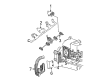
Chevrolet Suburban 2500 Fuel Rail
Want to cut long-term maintenance and repair costs? Choose OEM Fuel Rail. Those parts deliver top durability you can trust. On our site, you'll find a huge catalog of genuine Chevrolet Suburban 2500 parts. Prices are unbeatable, so you can keep more in your pocket. Every OEM Chevrolet Suburban 2500 Fuel Rail includes a manufacturer's warranty. You can also get an easy return policy that keeps buying risk free. Fast delivery, get your car on the road quickly. It's simple to search, compare, and order. Stop guessing about quality or fit. Order today and save with parts that last.
Chevrolet Suburban 2500 Fuel Rail Parts and Q&A
- Q: How to service the fuel rail assembly on Chevrolet Suburban 2500?A:The first step for servicing the Fuel Rail assembly involves lowering fuel system pressure while cleaning the assembly with gm x-30a engine cleaner along with other equivalent products without allowing it to sit in liquid cleaning solvent. The service procedure begins with removing the engine sight shield bracket nuts followed by unmounting the bracket and then disconnecting the generator harness connector and evaporative emission canister purge valve harness connector and throttle position sensor harness connector along with the electronic throttle control harness connector. After removing the bracket studs from the upper engine wire harness it should be positioned aside so that each connector can be identified with its matching injector based on firing sequence. Locate the white portion on each injector connector then grip and carefully lift the top section of connectors only until exceeding the white area. Next, press the lower tab to unlock the connector. The process starts by disconnecting both the fuel feed pipe and return pipe from the Fuel Rail as a first step followed by disconnection of the line that supplies vacuum to the fuel pressure regulator. First remove the Fuel Rail attaching bolts then take off the assembly before extracting one injector lower o-ring seat from each injector and discarding its seal. Clean engine oil must be used to lubricate new lower injector o-ring seals before placing them onto each injector spray tip. Install the Fuel Rail assembly to the Intake Manifold by applying gm p/n 12345382 (Canadian P/N 10953489) threadlock on the 5 mm (0.020 in) band of bolts with a torque of 12 n.m (106 lb in). Reinstall the fuel pressure regulator vacuum line together with the fuel feed and return pipes while verifying correct injector electrical placement for maintaining the engine firing sequence. Attach the upper engine wire harness bracket using its retainer studs and fasten up the nut to 10 n.m (89 lb in). The repair process requires reattachment of the generator harness connector along with the evap canister purge valve harness connector and throttle position sensor harness connector and electronic throttle control harness connector. Secure the engine sight shield mounting bracket bolts to 10 n.m (89 lb in) while tightening the nuts and fasten the fuel filler cap and connect the negative Battery Cable. A fuel leak inspection process begins with a two-second ignition on, followed by ten seconds of ignition off before repeating the procedure for visual inspection of fuel leakage. Mount the engine sight shield and fasten its bolts with a torque of 10 n.m (89 lb in).

Related Chevrolet Suburban 2500 Parts
 Chevrolet Suburban 2500 Air Filter
 Chevrolet Suburban 2500 Air Hose
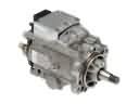 Chevrolet Suburban 2500 Fuel Injection Pump
 Chevrolet Suburban 2500 Fuel Injector
 Chevrolet Suburban 2500 Fuel Injector O-Ring
 Chevrolet Suburban 2500 Fuel Pressure Regulator
 Chevrolet Suburban 2500 Fuel Pump Seal
 Chevrolet Suburban 2500 Fuel Tank Lock Ring
 Chevrolet Suburban 2500 Idle Control Valve
 Chevrolet Suburban 2500 Throttle Body
 Chevrolet Suburban 2500 Throttle Body Gasket
 Chevrolet Suburban 2500 Throttle Cable